Page 2974 of 4264

0A-2 GENERAL INFORMATION
GENERAL REPAIR INSTRUCTIONS
1. Park the vehicle on level ground and chock the front or rear wheels before lifting the vehicle.
2. Raise the vehicle with a jack set against the axle or the frame.
3. Support the vehicle on chassis stands.
4. Use covers on the vehicle body, seats, and floor to prevent damage and/or contamination.
5. Disconnect the grounding cable from the battery before performing service operations.
This will prevent cable damage or burning due to short circuiting.
6. Handle brake fluid and antifreeze solution with great care.
Spilling these liquids on painted surfaces will damage the paint.
7. The use of the proper tool(s) and special tool(s) where specified is essential to efficient, reliable, and safe
service operations.
8. Always use genuine ISUZU replacement parts.
9. Discard used cotter pins, gaskets, O-rings, oil seals, lock washers, and self-locking nuts at disassembly.
Normal function of these parts cannot be guaranteed if they are reused.
10. Prepare new cotter pins, gaskets, O-rings, oil seals, lock washers, and self-locking nuts for installation.
11. Keep the disassembled parts neatly in groups.
This will facilitate smooth and correct reassembly.
12. Keep fixing nuts and bolts separate.
Fixing nuts and bolts vary in hardness and design according to installation position.
13. Clean all parts before inspection or reassembly.
14. Clean the oil ports and other openings with compressed air to make certain that they are free from dirt and
obstructions.
15. Lubricate the rotating and sliding faces of all moving parts with oil or grease before installation.
16. Use the recommended liquid gasket to prevent leakage.
17. Carefully observe all nut and bolt torque specifications.
18. When removing or replacing parts that require refrigerant to the discharged from the Air conditioning system, be
sure to use the Vehicle Refrigerant Recovery and Recycling Equipment (VRRRE) to recover and recycle R134a,
to promote the movement for the protection of the ozone layer covering the earth.
19. Check and recheck your work. No service operation is complete until you have done this.
Page 3036 of 4264

1-26 HEATER AND AIR CONDITIONING
ON-VEHICLE SERVICE
PRECAUTIONS FOR REPLACEMENT OR
REPAIR OF AIR CONDITIONING PARTS
There are certain procedures, practices and precautions that
should be followed when servicing air conditioning systems:
�
Keep your work area clean.
�
Always wear safety goggle and protective gloves when
working on refrigerant systems.
� Beware of the danger of carbon monoxide fumes caused by
running the engine.
�
Beware of discharged refrigerant in enclosed or improperly
ventilated garages.
�
Always disconnect the negative battery cable and discharge
and recover the refrigerant whenever repairing the air
conditioning system.
�
When discharging and recovering the refrigerant, do not
allow refrigerant to discharge too fast; it will draw
compressor oil out of the system.
�
Keep moisture and contaminants out of the system. When
disconnecting or removing any lines or parts, use plugs or
caps to close the fittings immediately.
Never remove the caps or plugs until the lines or parts are
reconnected or installed.
�
When disconnecting or reconnecting the lines, use two
wrenches to support the line fitting, to prevent from twisting
or other damage.
�
Always install new O-rings whenever a connection is
disassembled.
�
Before connecting any hoses or lines, apply new specified
compressor oil to the O-rings.
�
When removing and replacing any parts which require
discharging the refrigerant circuit, the operations described
in this section must be performed in the following sequence:
1) Using the ACR
4 (HFC-134a Refrigerant Recovery/
Recycling/Recharging/System) or equivalent to
thoroughly discharge and recover the refrigerant.
ACR
4 (115V 60Hz) : 5-8840-0629-0 (J-39500-A)
ACR4 (220-240V 50/60Hz)
: 5-8840-0630-0 (J-39500-220A)
ACR
4 (220-240V 50/60Hz Australian model)
: 5-8840-0631-0 (J-39500-220ANZ)
2) Remove and replace the defective part.
3)
After evacuation, charge the air conditioning system and
check for leaks.
Page 3086 of 4264
1-76 HEATER AND AIR CONDITIONING
INSPECTION AND REPAIR
840R300005-X
Resistor
As for air-conditioning model, fixed on left (RHD) / right (LHD)
side of the evaporator unit.
As for heater only model, fixed on left (RHD) / right (LHD) side
of the duct placed between blower unit and heater unit.
Replace the resistor with a new on if the coil is found to be
open or if the resistance value deviates from the specified
range.
Terminal Resistance
3 – 2 1.99 �
3 – 4 0.9 �
3 – 1 0.17 �
Blower motor
Check blower motor for smooth rotation.
Connect the battery positive terminal to the No.1 terminal of the
blower motor and negative to the No.2.
Be sure to check to see if the blower motor operates correctly.
Page 3088 of 4264
1-78 HEATER AND AIR CONDITIONING
RTW4A0SH000201
Pressure switch
Disconnect pressure switch connector and check for continuity
between pressure switch side connector terminal.
825r300045
Heater and thermo switch relay.
Check for continuity between the relay terminals.
1 - 5 �����
No continuity
(When battery voltage is applied between 2 - 4 )
1 - 5 �����
Continuity
825r300023
Check for continuity between the relay terminals.
1 - 2 �����
No continuity
(When battery voltage is applied between 3 - 4 )
1 - 2 �����
Continuity
Page 3090 of 4264
1-80 HEATER AND AIR CONDITIONING
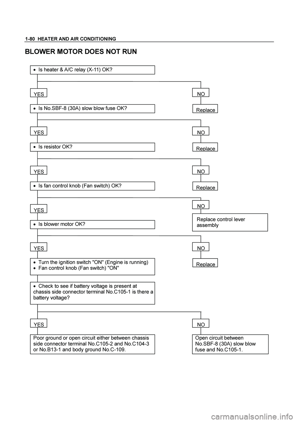
BLOWER MOTOR DOES NOT RUN
Replace
YES
� Is No.SBF-8 (30A) slow blow fuse OK?
��Is heater & A/C relay (X-11) OK?
YES
� Is resistor OK?
YES
� Is fan control knob (Fan switch) OK?
YES
YES
� Check to see if battery voltage is present at
chassis side connector terminal No.C105-1 is there a
battery voltage?
� Turn the ignition switch "ON" (Engine is running)
� Fan control knob (Fan switch) "ON"
� Is blower motor OK?
YES
Poor ground or open circuit either between chassis
side connector terminal No.C105-2 and No.C104-3
or No.B13-1 and body ground No.C-109.
NO
Replace
NO
Replace
NO
NO
Replace control lever
assembly
Replace
NO
NO
Open circuit between
No.SBF-8 (30A) slow blow
fuse and No.C105-1.
Page 3100 of 4264
1-90 HEATER AND AIR CONDITIONING
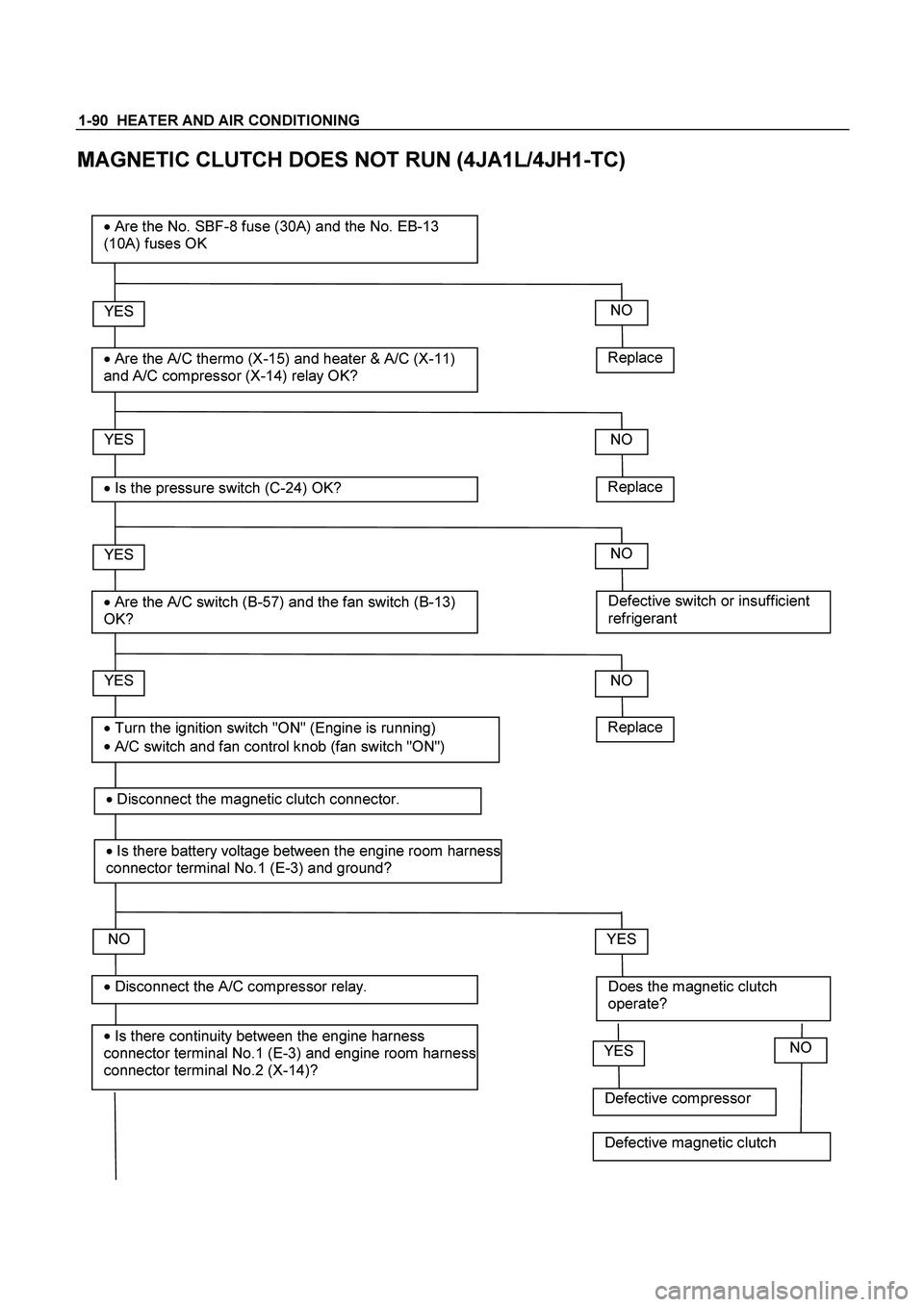
MAGNETIC CLUTCH DOES NOT RUN (4JA1L/4JH1-TC)
Replace
YES
�
Are the A/C thermo (X-15) and heater & A/C (X-11)
and A/C compressor (X-14) relay OK?
� Are the No. SBF-8 fuse (30A) and the No. EB-13
(10A) fuses OK
YES
�
Is the pressure switch (C-24) OK?
YES
�
Are the A/C switch (B-57) and the fan switch (B-13)
OK?
NO
YES
�
Is there continuity between the engine harness
connector terminal No.1 (E-3) and engine room harness
connector terminal No.2 (X-14)?
� Disconnect the A/C compressor relay.
� Turn the ignition switch "ON" (Engine is running)
�
A/C switch and fan control knob (fan switch "ON")
NO
Replace
NO
Defective switch or insufficient
refrigerant
NO
NO
Does the magnetic clutch
operate?
YES
Replace
�
Disconnect the magnetic clutch connector.
� Is there battery voltage between the engine room harness
connector terminal No.1 (E-3) and ground?
Defective compressor
YESNO
Defective magnetic clutch
Page 3101 of 4264

and engine room harness connector
terminal No.2 (X-14).
YES
�
Is there battery v")
HEATER AND AIR CONDITIONING 1-91
Open circuit between the engine
harness connector terminal No.1 (E-3)
and engine room harness connector
terminal No.2 (X-14).
YES
�
Is there battery voltage between the engine room
harness connector terminal No.1 (X-14) and
ground?
YES
�
Disconnect the A/C thermo relay.
YES
�
Is there continuity between the ECM harness
connector terminal No.38 (C-56) and engine
room harness connector terminal No.4 (X-14)?
NO
Open circuit between the No. EB-13
fuse and engine room harness
connector terminal No.1 (X-14).
NO
Open circuit between the engine room
harness connector terminal No.1 (X-
15) and engine room harness
connector terminal No. 3 (X-14).
NO
� Is there continuity between the engine room
harness connector terminal No.3 (X-14) and No.1
(X-15)?
YES
�
Is there continuity between the ECM harness
connector terminal No.30 (C-56) and engine
room harness connector terminal No.2 (X-15)? Open circuit between the engine room
harness connector terminal No.1 (X-
15) and engine room harness
connector terminal No. 3 (X-14).
NO
YES
�
Is there battery voltage between the engine room
harness connector terminal No.4 (X-15) and
ground?
Open circuit between the ECM
harness connector No. 38 (C-56) and
engine room harness connector
terminal No. 4 (X-14).
NO
YES
�
Is there continuity between the engine room
harness connector terminal No. 3 (X-15) and the
engine room harness connector terminal No. 1 (C-
24).
Open circuit between the No. EB-13
fuse and engine room harness
connector terminal No. 4 (X-15).
NO
�
Disconnect the ECM harness connector.
�
Disconnect the pressure switch?
Page 3102 of 4264

1-92 HEATER AND AIR CONDITIONING
YES
� Disconnect the condenser fan relay connector
condenser fan.
YES
�
Is there battery voltage between the engine
room harness connector terminal NO.3 (C-
24) and ground? Open circuit between the condenser
fan relay 4JH1TC No.4 (X-6) 4JA1L
No. 3 (X-13) and engine room harness
connector terminal No. 4 (X-14).
NO
� Is there continuity between the relay terminal
4JH1TC No. 4 (X-6) 4JA1L No.3 (X-13)and
engine room harness connector terminal No.4
(C-24)?
YES
�
connect the A/C thermo relay connector.
Open circuit between the No. EB-13
fuse and engine room harness
connector terminal No. 3 (C-24).
NO
YES
�
Is there battery voltage between the engine
room harness connector terminal No.3 (C-55)
dd?
Open circuit between the engine room
harness connector terminal No. 2 (C-
55) and the engine room harness
connector terminal No. 2 (C-24).
NO
YES
�
Is there continuity between the engine room
harness connector terminal No.1 (C-55) and
ground (C-109) ? or (cooler only) the short
connector terminal No.3 (B-79) and ground (C-
109
)?
Open circuit between the No. EB-13
fuse and engine room harness
connector terminal No. 3 (C-55).
NO
�
Disconnect the electronic themostat.
�
Is there continuity between the engine room
harness connector terminal No. 2 (C-55) and the
engine room harness connector terminal No. 2
(C-24).
Open circuit between and engine room
harness connector terminal No. 3 (X-
15) and the engine room harness
connector terminal No. 1(C-24).
NO
 / right (LHD)
side of the evaporator unit.
As for he")