Page 3686 of 4264
7A2-6 TRANSMISSION CONTROL SYSTEM (AW30 –40LE) (V6 3.5L)
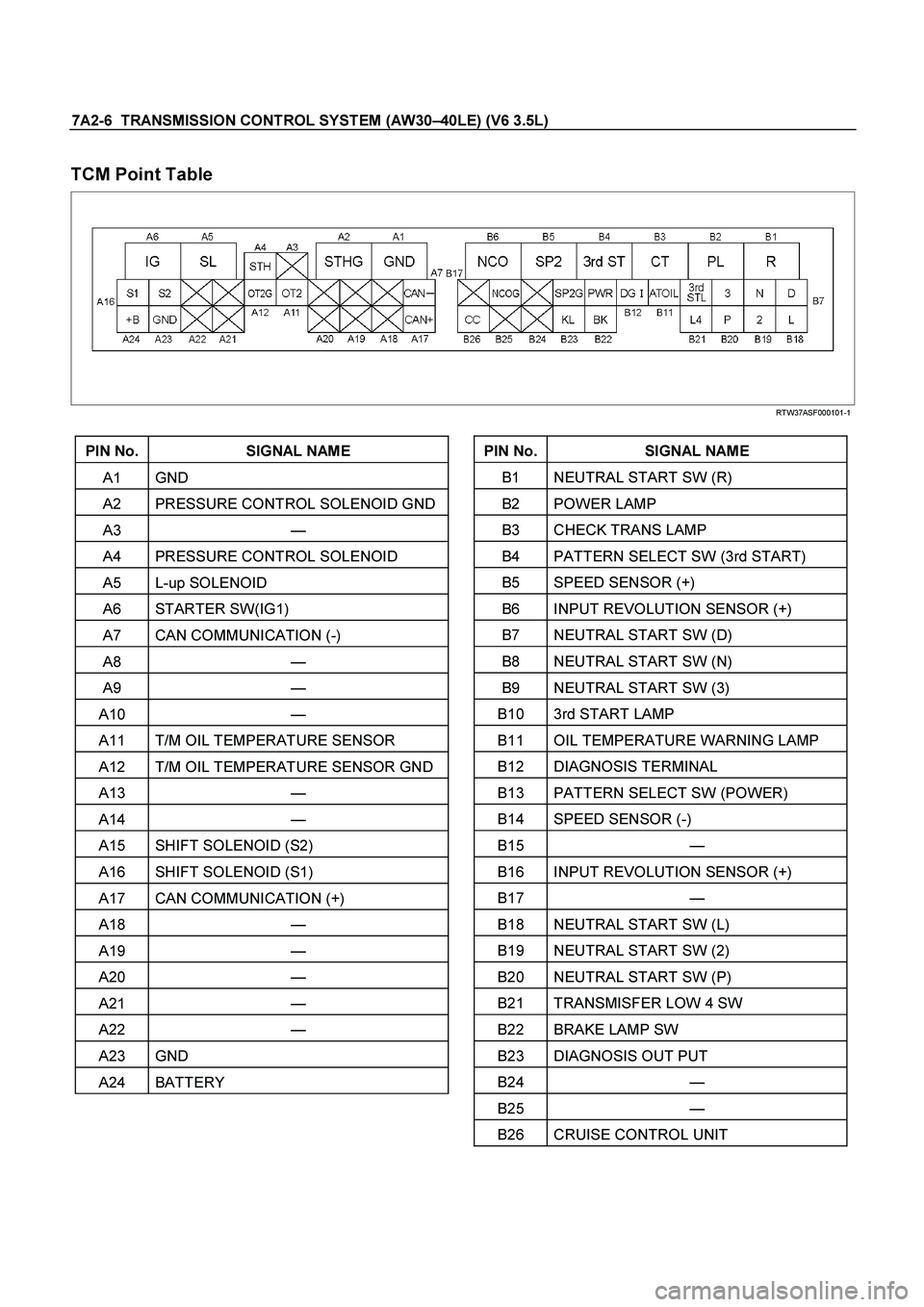
TCM Point Table
RTW37ASF000101-1
PIN No. SIGNAL NAME
A1 GND
A2 PRESSURE CONTROL SOLENOID GND
A3 —
A4 PRESSURE CONTROL SOLENOID
A5 L-up SOLENOID
A6 STARTER SW(IG1)
A7 CAN COMMUNICATION (-)
A8 —
A9 —
A10 —
A11 T/M OIL TEMPERATURE SENSOR
A12 T/M OIL TEMPERATURE SENSOR GND
A13 —
A14 —
A15 SHIFT SOLENOID (S2)
A16 SHIFT SOLENOID (S1)
A17 CAN COMMUNICATION (+)
A18 —
A19 —
A20 —
A21 —
A22 —
A23 GND
A24 BATTERY
PIN No. SIGNAL NAME
B1 NEUTRAL START SW (R)
B2 POWER LAMP
B3 CHECK TRANS LAMP
B4 PATTERN SELECT SW (3rd START)
B5 SPEED SENSOR (+)
B6 INPUT REVOLUTION SENSOR (+)
B7 NEUTRAL START SW (D)
B8 NEUTRAL START SW (N)
B9 NEUTRAL START SW (3)
B10 3rd START LAMP
B11 OIL TEMPERATURE WARNING LAMP
B12 DIAGNOSIS TERMINAL
B13 PATTERN SELECT SW (POWER)
B14 SPEED SENSOR (-)
B15 —
B16 INPUT REVOLUTION SENSOR (+)
B17 —
B18 NEUTRAL START SW (L)
B19 NEUTRAL START SW (2)
B20 NEUTRAL START SW (P)
B21 TRANSMISFER LOW 4 SW
B22 BRAKE LAMP SW
B23 DIAGNOSIS OUT PUT
B24 —
B25 —
B26 CRUISE CONTROL UNIT
Page 3695 of 4264
TRANSMISSION CONTROL SYSTEM (AW30 –40LE) (V6 3.5L) 7A2-15
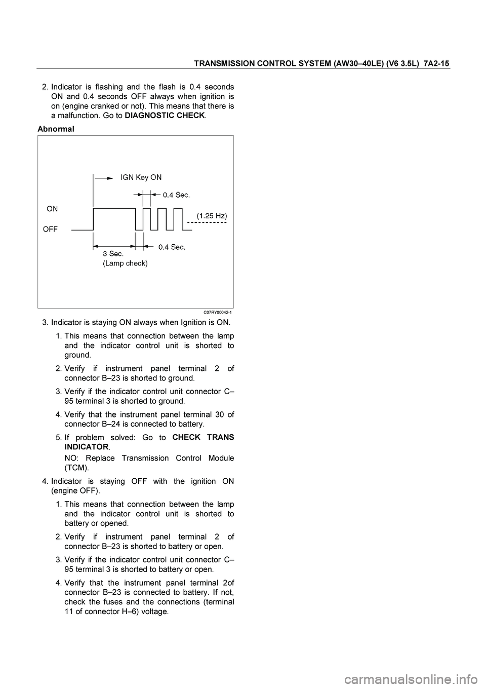
2. Indicator is flashing and the flash is 0.4 seconds
ON and 0.4 seconds OFF always when ignition is
on (engine cranked or not). This means that there is
a malfunction. Go to DIAGNOSTIC CHECK
.
Abnormal
C07RY00042-1
3. Indicator is staying ON always when Ignition is ON.
1. This means that connection between the lamp
and the indicator control unit is shorted to
ground.
2. Verify if instrument panel terminal 2 o
f
connector B –23 is shorted to ground.
3. Verify if the indicator control unit connector C –
95 terminal 3 is shorted to ground.
4.
Verify that the instrument panel terminal 30 of
connector B –24 is connected to battery.
5. If problem solved: Go to CHECK TRANS
INDICATOR .
NO: Replace Transmission Control Module
(TCM).
4. Indicator is staying OFF with the ignition ON
(engine OFF).
1. This means that connection between the lamp
and the indicator control unit is shorted to
battery or opened.
2.
Verify if instrument panel terminal 2 of
connector B –23 is shorted to battery or open.
3. Verify if the indicator control unit connector C –
95 terminal 3 is shorted to battery or open.
4.
Verify that the instrument panel terminal 2of
connector B –23 is connected to battery. If not,
check the fuses and the connections (terminal
11 of connector H –6) voltage.
Page 3707 of 4264
TRANSMISSION CONTROL SYSTEM (AW30 –40LE) (V6 3.5L) 7A2-27
SERVICE PROGRAMMING SYSTEM (SPS)
The procedure to program the control unit by using the
Service Programming System (SPS) software
contained in TIS2000 is explained below.
NOTE: �
� �
�
Should Tech2 display "SPS Procedure was not
successful", engine will not start, but no DTCs
are present, low battery voltage or poo
r
electrical connections should be the primary
suspects. Perform the SPS procedure again
after rectifying the fault/s.
IMPORTANT:
Perform the following checks before attempting to
program the control unit:
�
� �
�
The Tech2 PCMCIA card is programmed with
the latest software release.
�
� �
�
The latest release of TIS2000 is loaded on the
PC.
�
� �
�
The vehicle battery is fully charged.
�
� �
�
The control unit to be programmed is
connected to the vehicle.
1. Preparations of TIS 2000
1.
Connect Tech 2 to P/C.
2.
Check to see if Hardware Key is plugged into Port.
3.
Activate TIS 2000 by P/C.
4.
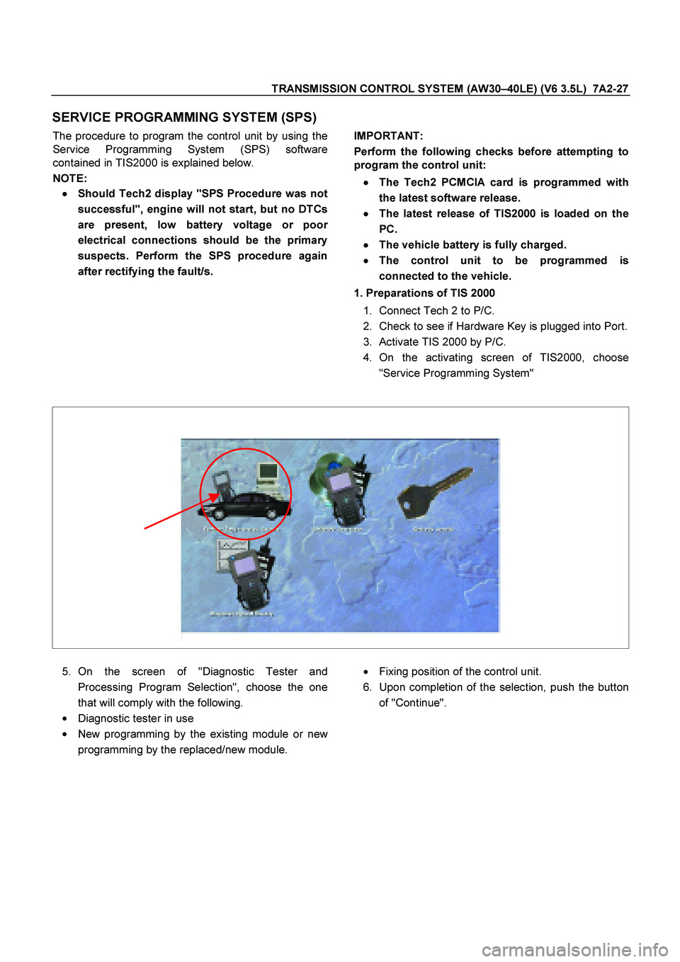
On the activating screen of TIS2000, choose
"Service Programming System"
5.
On the screen of "Diagnostic Tester and
Processing Program Selection", choose the one
that will comply with the following.
�
Diagnostic tester in use
�
New programming by the existing module or new
programming by the replaced/new module.
�
Fixing position of the control unit.
6.
Upon completion of the selection, push the button
of "Continue".
Page 3711 of 4264
TRANSMISSION CONTROL SYSTEM (AW30 –40LE) (V6 3.5L) 7A2-31
16 – Terminal Data Link Connector (DLC)
OBD standardizes Data Link Connector (DLC)
configurations. The DLC, formerly referred to as the
ALDL, will be a 16 –terminal connector found on the
lower right side of the driver's side instrument panel. All
manufacturers must conform to this 16 –terminal
standard.
060R300015
810RT022
PIN 1 – uart
PIN 2 – J1850 Bus + L line on 2–wire systems, or single wire (ECM)
PIN 3 – (Not used)
PIN 4 – Chassis ground pin
PIN 5 – Chassis ground pin
PIN 6 – ECM diagnostic enable
PIN 7 – KW2000
PIN 8 – (Not used)
PIN 9 – Primary UART
PIN 10 – (Not used)
PIN 11 – TCM diagnostic enable
PIN 12 – ABS diagnostic or CCM diagnostic enable
PIN 13 – SIR diagnostic enable
PIN 14 – (Not used)
PIN 15 – (Not used)
PIN 16 – Battery power from vehicle unswitched (4 AMP MAX.)
Page 3716 of 4264
7A2-36 TRANSMISSION CONTROL SYSTEM (AW30–40LE) (V6 3.5L)
Diagnostic Aids
Inspect the wiring for poor electrical connection at
the TCM. Look for possible bent, backed out,
deformed or damaged terminals. Check for weak
terminal tension as well. Also check for a chafed wire
that could short to bare metal or other wiring.
Inspect for a broken wire inside the insulation.
DTC P0560 – System Voltage Error
Step Action Value(s) YES NO
1
Was the powertrain On-Board Diagnostic (OBD)
System Check performed? — Go to Step 2 Go to OBD
System Check
2 Using a DVM, measure the battery voltage at the
battery.
Is the battery voltage greater than the specified
value? 11.5 V Go to Step 3 Charge battery,
then go to Step
3
3
1. Install a Tech 2.
2. Select “Ignition Volts" on the Tech 2.
3. Start the engine and raise the engine speed to the
specified value.
4. Load the electrical system by turning on the
headlights, high blower, etc.
Is the ignition voltage approximately equal to the
specified value? 2000 RPM
12.8-14.1 VGo to Step 4 Go to
Starting/Chargi
ng
4
1. Ignition “OFF".
2. Disconnect the TCM connector at the TCM.
3. Using a DVM, measure the battery voltage at the
TCM connector C-94.
Is it approximately equal to battery voltage? — Check for
excessive
curren draw
with ignition
“OFF" engine
“OFF". Go to Step 5
5
1. Check for faulty connections at the TCM harness
terminals.
2. Repair as necessary.
Was a repair necessary? — Verify repair Go to Step 6
6 Check for an open battery feed circuit to the TCM.
Is the action complete? — Verify repair Go to Step 7
7 Replace the TCM.
Important:
The replacement TCM must be
programmed. (Refer to SPS for procedure.)
Is the action complete? — Verify repair —
Page 3779 of 4264
ON-VEHICLE SERVICE (AW30 –40LE) 7A3-23
Neutral Start Switch (Mode Switch)
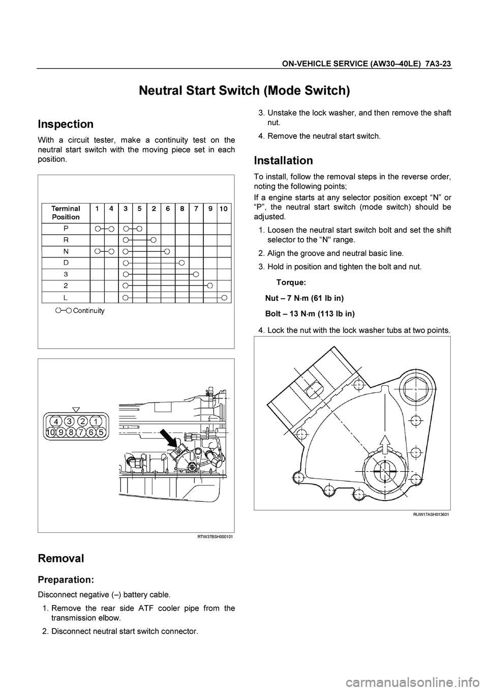
Inspection
With a circuit tester, make a continuity test on the
neutral start switch with the moving piece set in each
position.
RTW37BSH000101
Removal
Preparation:
Disconnect negative ( –) battery cable.
1. Remove the rear side ATF cooler pipe from the
transmission elbow.
2. Disconnect neutral start switch connector.
3. Unstake the lock washer, and then remove the shaft
nut.
4. Remove the neutral start switch.
Installation
To install, follow the removal steps in the reverse order,
noting the following points;
If a engine starts at any selector position except “N ” o
r
“ P ”, the neutral start switch (mode switch) should be
adjusted.
1. Loosen the neutral start switch bolt and set the shift
selector to the “N" range.
2. Align the groove and neutral basic line.
3. Hold in position and tighten the bolt and nut.
Torque:
Nut – 7 N �
��
�
m (61 Ib in)
Bolt – 13 N �
��
�
m (113 Ib in)
4. Lock the nut with the lock washer tubs at two points.
RUW17ASH013601
Page 3782 of 4264
7A3-26 ON-VEHICLE SERVICE (AW30 –40LE)
Solenoid
Inspection
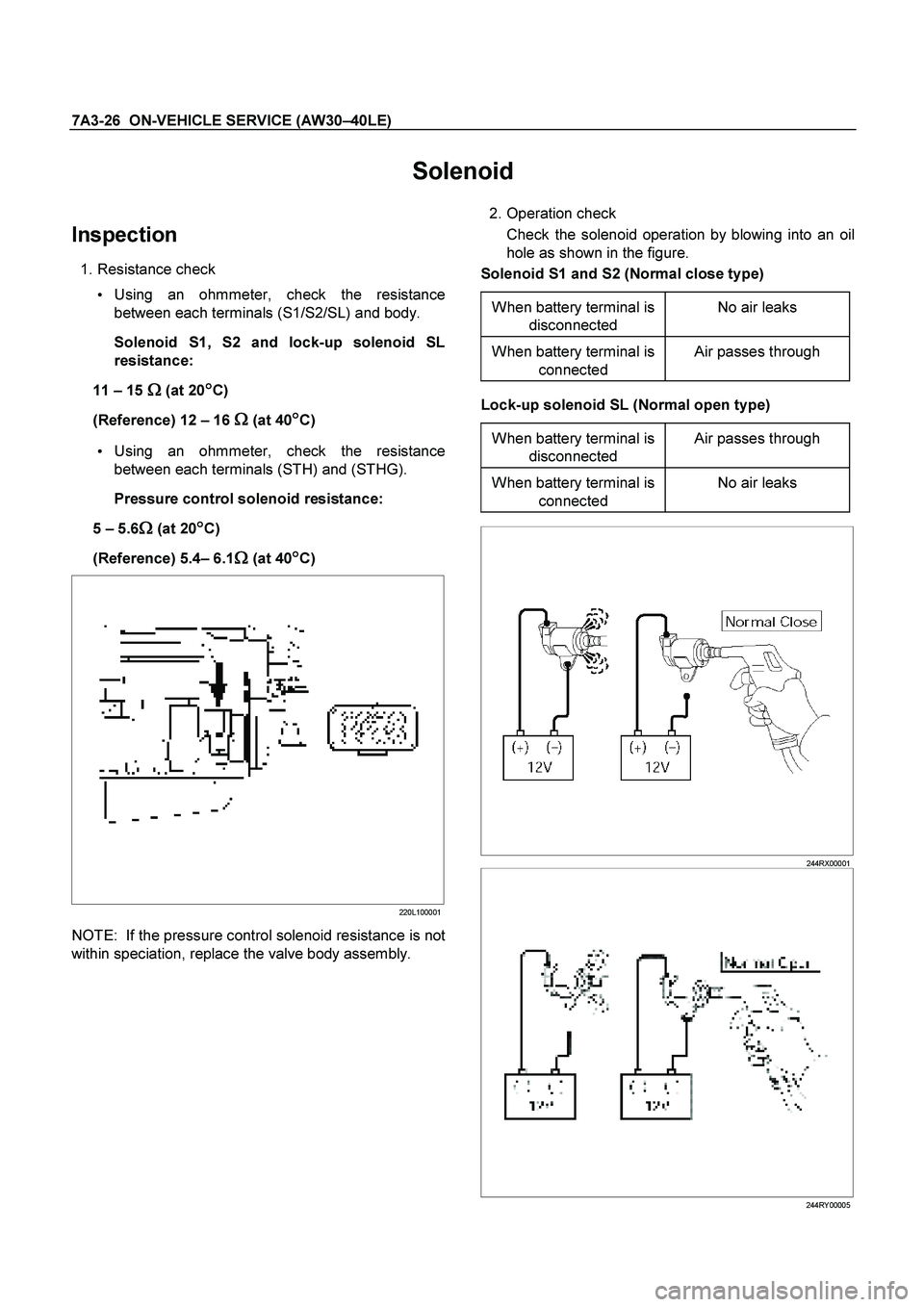
1. Resistance check
Using an ohmmeter, check the resistance
between each terminals (S1/S2/SL) and body.
Solenoid S1, S2 and lock-up solenoid SL
resistance:
11 – 15
�
� �
� (at 20�
� �
�C)
(Reference) 12 – 16
�
� �
� (at 40�
� �
�C)
Using an ohmmeter, check the resistance
between each terminals (STH) and (STHG).
Pressure control solenoid resistance:
5 – 5.6
�
� �
� (at 20�
� �
�C)
(Reference) 5.4 – 6.1
�
� �
� (at 40�
� �
�C)
220L100001
NOTE: If the pressure control solenoid resistance is not
within speciation, replace the valve body assembly.
2. Operation check
Check the solenoid operation by blowing into an oil
hole as shown in the figure.
Solenoid S1 and S2 (Normal close type)
When battery terminal is disconnected No air leaks
When battery terminal is
connected Air passes through
Lock-up solenoid SL (Normal open type)
When battery terminal is disconnected Air passes through
When battery terminal is
connected No air leaks
244RX00001
244RY00005
Page 3784 of 4264
7A3-28 ON-VEHICLE SERVICE (AW30 –40LE)
Select Lever
RTW37ALF001101
Legend
(6) Base plate
(1) Rear console
(7) Grooved pin
(2) Front console
(8) Spring plate
(3) Select lever knob
(9) Lever assembly
(4) Upper housing
(10) Sleeve
(5) Lamp assembly
Remove or Disconnect
1.
Block the wheels.
2.
Disconnect the negative battery cable.
3.
Remove the rear console and the front console.
4.
Remove the 2 screws fixing the select lever knob.
5.
Remove the knob together with the knob button and
spring from the lever.
6.
Turn the sleeve counterclockwise to remove it. Make
a note of the number of turns required to free the
sleeve.
7.
Remove the harness connectors from the base plate.