Page 1307 of 4264
:
A Bosch Distributor Type Injection Pump is used. A single reciprocating/revolving plunger delivers the fuel uniformly
to th")
FUEL SYSTEM 6C – 7
INJECTION PUMP
RTW46CLF000201
4JA1T(L):
A Bosch Distributor Type Injection Pump is used. A single reciprocating/revolving plunger delivers the fuel uniformly
to the injection nozzles, regardless of the number of cylinders.
The governor, the injection timer, and the feed pump are all contained in the injection pump housing. The injection
pump is compact, light weight, and provides reliable high-speed operation.
The vacuum-type fast idle actuator increases the engine idling speed to provide the additional power required to
operate the air conditioner.
Fast idler diaphragm movement is caused by changes in the negative pressure created by the engine’s vacuum
pump.
The diaphragm motion is transferred to the injection pump control lever to increase or decrease the idling speed.
4JA1TC/4JH1TC:
The Bosch VP44 injection pump is electronically controlled. The pump controller combine to injection pump.
Signals from the pump controller are sent to the engine control module (ECM). In response to these signals, the
ECM selects the optimum fuel injection timing and volume for the existing driving conditions.
Page 1308 of 4264
6C – 8 FUEL SYSTEM
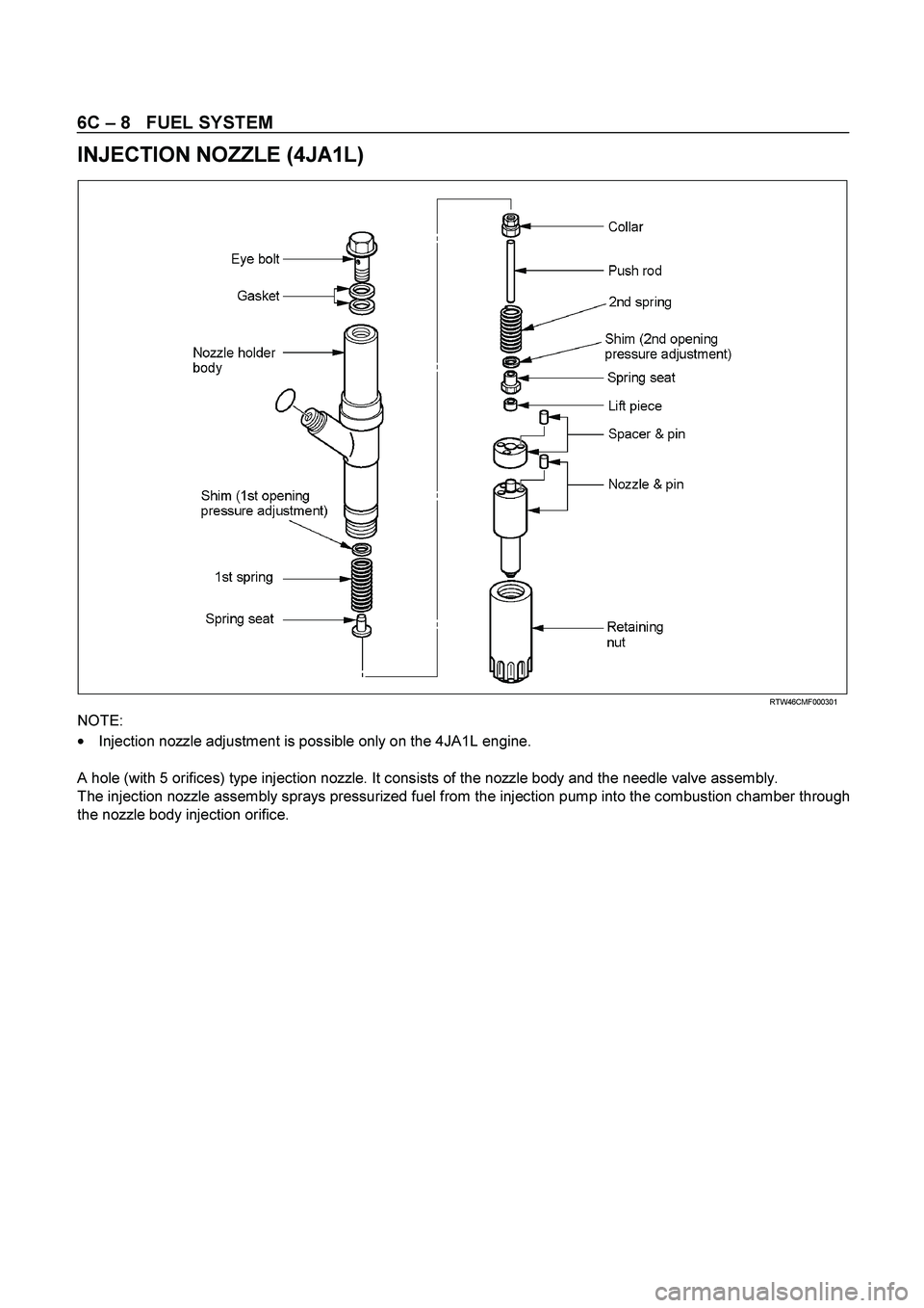
INJECTION NOZZLE (4JA1L)
RTW46CM F000301
NOTE:
�
Injection nozzle adjustment is possible only on the 4JA1L engine.
A hole (with 5 orifices) type injection nozzle. It consists of the nozzle body and the needle valve assembly.
The injection nozzle assembly sprays pressurized fuel from the injection pump into the combustion chamber through
the nozzle body injection orifice.
Page 1310 of 4264

6C – 10 FUEL SYSTEM
Removal
CAUTION: When repair to the fuel system has been
completed, start engine and check the fuel system for
loose connection or leakage. For the fuel system
diagnosis, see Section “Driveability and Emission".
1. Disconnect battery ground cable.
2. Loosen slowly the fuel filler cap.
NOTE: Be careful not to spouting out fuel because of change
the pressure in the fuel tank.
NOTE: Cover opening of the filler neck to prevent any dus
t
entering.
3. Jack up the vehicle.
4. Support underneath of the fuel tank with a lifter.
5. Remove the inner liner of the wheel house at rear left side.
6. Remove fixing bolt of the filler neck from the body.
7.
Disconnect the quick connector (3) of the fuel tube from the
fuel pipe.
NOTE: Cover the quick connector to prevent any dust entering
and fuel leakage.
NOTE: Refer to“Fuel Tube/Quick Connector Fittings” in this
section when performing any repairs.
8. Remove fixing bolt (1) of the tank band and remove the
tank band (2).
9.
Disconnect the pump and sender connector on the fuel
pump and remove the harness from weld clip on the fuel
tank.
10.
Lower the fuel tank (5).
NOTE: When lower the fuel tank from the vehicle, don’t scratch
each hose and tube by around other parts.
Installation
1. Raise the fuel tank.
NOTE: When raise the fuel tank to the vehicle, don’t scratch
each hose and tube by around other parts.
2. Connect the pump and sender connector to the fuel pump
and install the harness to weld clip on the tank.
NOTE: The connector must be certainly connected agains
t
stopper.
3. Install the tank band and fasten bolt.
Torque N·m (kg·m / lb ft)
68 (6.9 / 50)
NOTE: The anchor of the tank band must be certainly installed
to guide hole on frame.
4. Connect the quick connector of the fuel tube to the fuel pipe
and the evapo tube from evapo joint connector.
NOTE: Pull off the left checker on the fuel pipe.
NOTE: Refer to “Fuel Tube/Quick Connector Fittings” in this
section when performing any repairs.
Page 1319 of 4264
FUEL SYSTEM 6C – 19
INJECTION PUMP
REMOVAL AND INSTALLATION
Read this Section carefully before performing any removal and installation procedure. This Section gives you
important points as well as the order of operation. Be sure that you understand everything in this Section before you
begin.
Removal
1. Battery
Remove the battery from the battery tray.
6C-1
2. Drive Belt 1) Loosen the adjust bolt of the power steering pump pulley.
2) Remove the drive belt.
3. Power Steering Pump Assembly
P1010003
4. Accelerator Control Cable
Disconnect the accelerator cable from the intake throttle.
5. Vacuum Hose
Disconnect the vacuum hose from the EGR valve and the intake throttle.
6. Fan
Page 1320 of 4264

Disconnect the harness connector from the throttle
positi")
6C – 20 FUEL SYSTEM
7. Power Steering Pump Bracket
6C-4 8. Throttle Position Sensor Harness Connector
(4JA1TC/4JH1TC only)
Disconnect the harness connector from the throttle
position sensor.
9. Oil Level Gauge
10. Fuel Pipe
1) Disconnect the fuel hoses from the fuel filter or priming
pump.
2) Disconnect the fuel hoses from the injection pump.
11. Fuel Filter Assembly (Except EURO III model)
6C-5
12. Fuel Filter Bracket (Except EURO III model)
13. Leak Off Hose
Disconnect the leak off hose at the injection pump.
14. Injection Pipe Clip
15. Injection Pipe
1) Loosen the injection pipe sleeve nuts at the delivery
valve side and the injection nozzle side.
Note:
Do not apply excessive force to the injection pipes.
2) Loosen the injection pipe clip.
3) Remove the injection pipes.
Note:
Plug the delivery holder ports with the caps to prevent
the entry of foreign material.
16. Intake Manifold
1) Remove the EGR valve from the intake manifold and
EGR pipe.
2) Loosen the intake rubber hoses clip.
3) Loosen the intake manifold bolts and nuts.
17. Injection Pump Cover (4JA1TC/4JH1TC only)
Page 1321 of 4264
FUEL SYSTEM 6C – 21
020L200017
RTW46CSH000201
18. Timing Check Hole Cover
1) Remove the timing check hole cover.
2) For ease in reinstalling the injection pump, align the
timing mark on the timing gear case cover by turning
the crankshaft using wrench.
And bring the piston in the No.1 cylinder to TDC on the
compression stroke by turning the crankshaft until the
crankshaft pulley TDC line aligned with the timing
mark.
Note:
If the check hole cover is reinstalled with the lock bolt
still in place, the crank pulley will not turn.
6C-7
3) Insert the lock bolt (M6 x 30) into the scissors gear idle
gear “B” fixing hole to prevent the scissors gear from
turning.
29. Injection Pump Bracket
20. Injection Pump
Page 1322 of 4264
6C – 22 FUEL SYSTEM
RTW46CSH000201
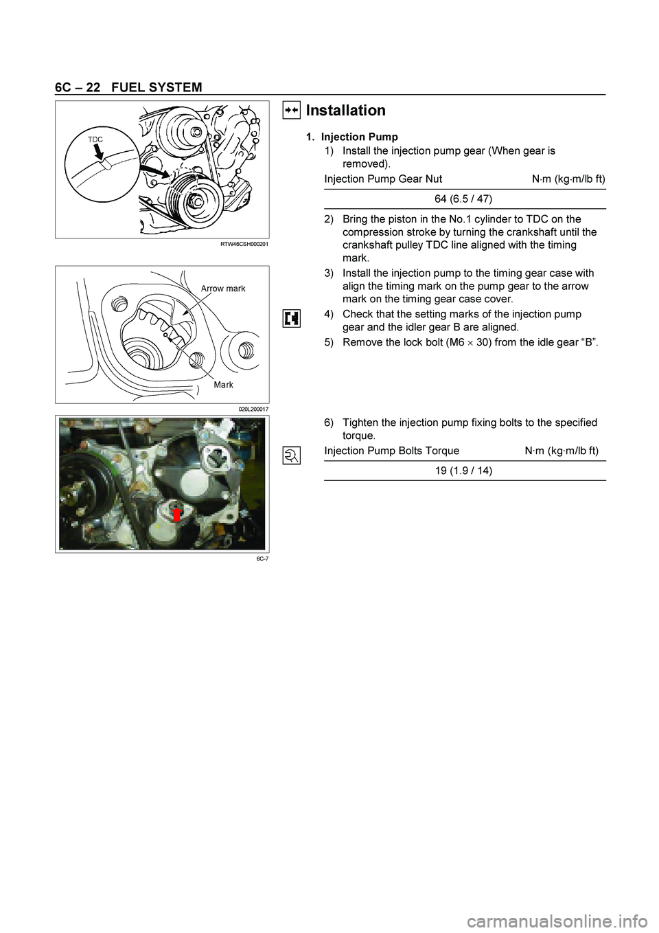
Installation��
1. Injection Pump
1) Install the injection pump gear (When gear is
removed).
Injection Pump Gear Nut N�
m (kg�
m/lb ft)
64 (6.5 / 47)
2) Bring the piston in the No.1 cylinder to TDC on the
compression stroke by turning the crankshaft until the
crankshaft pulley TDC line aligned with the timing
mark.
020L200017
3) Install the injection pump to the timing gear case with
align the timing mark on the pump gear to the arrow
mark on the timing gear case cover.
4) Check that the setting marks of the injection pump
gear and the idler gear B are aligned.
5) Remove the lock bolt (M6 �
30) from the idle gear “B”.
6C-7
6) Tighten the injection pump fixing bolts to the specified
torque.
Injection Pump Bolts Torque N·m (kg·m/lb ft)
19 (1.9 / 14)
Page 1323 of 4264

RTW46CSH000101
4JA1TC/4JH1TC
RTW36AMH000101
2. Injection Pump Bracket
1) Install the injection pump")
FUEL SYSTEM 6C – 23
4JA1T (L)
RTW46CSH000101
4JA1TC/4JH1TC
RTW36AMH000101
2. Injection Pump Bracket
1) Install the injection pump bracket (6) and the bracket
bolts (7) and (8) to the cylinder body. Temporarily
tighten the bracket bolts.
2) Tighten the bracket bolts (7) to the specified torque.
3) Tighten the bracket bolts (8) to the specified torque.
Note:
Tighten the bracket bolt (8) first.
Injection Pump Bracket Torque N·m(kg·m / lb ft)
(8) 19 (1.9 / 14)
(7) 40 (4.1 / 30)
3. Timing Check Hole Cover
Install the timing check hole cover and tighten bolts to the
specified torque.
Timing Check Hole Cover Bolts
Torque N·m(kg·m / lb ft)
8 (0.8 / 69)
4. Injection Pump Cover (4JA1TC/4JH1TC only)
5. Intake Manifold
1) Install the intake manifold with gasket.
Intake Manifold Bolts
Torque N·m(kg·m / lb ft)
19 (1.9 / 14)
Intake Manifold Nuts Torque N·m(kg·m / lb ft)
24 (2.4 / 17)
2) Install the EGR valve to the intake manifold and EGR
pipe temporarily.
3) Tighten the nuts and bolts to the specified torque
Torque N�m (kg�m/lb ft)
Nuts 24 (2.4/17)
Bolts 27 (2.8/20)

 Remove the timing check hole cover.
2) For ease in reinstalling the injection pump, align the
t")