2004 ISUZU TF SERIES fuel pump
[x] Cancel search: fuel pumpPage 1324 of 4264
6C – 24 FUEL SYSTEM
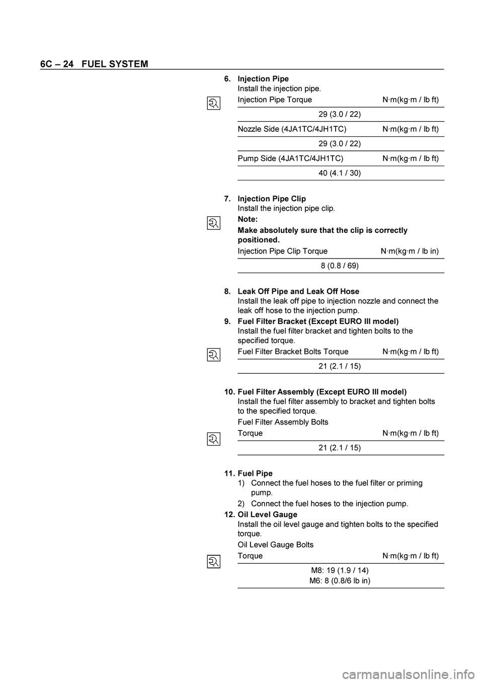
6. Injection Pipe
Install the injection pipe.
Injection Pipe Torque N·m(kg·m / lb ft)
29 (3.0 / 22)
Nozzle Side (4JA1TC/4JH1TC) N·m(kg·m / lb ft)
29 (3.0 / 22)
Pump Side (4JA1TC/4JH1TC) N·m(kg·m / lb ft)
40 (4.1 / 30)
7. Injection Pipe Clip
Install the injection pipe clip.
Note:
Make absolutely sure that the clip is correctly
positioned.
Injection Pipe Clip Torque N·m(kg·m / lb in)
8 (0.8 / 69)
8. Leak Off Pipe and Leak Off Hose
Install the leak off pipe to injection nozzle and connect the
leak off hose to the injection pump.
9. Fuel Filter Bracket (Except EURO III model)
Install the fuel filter bracket and tighten bolts to the
specified torque.
Fuel Filter Bracket Bolts Torque N·m(kg·m / lb ft)
21 (2.1 / 15)
10. Fuel Filter Assembly (Except EURO III model)
Install the fuel filter assembly to bracket and tighten bolts
to the specified torque.
Fuel Filter Assembly Bolts
Torque N·m(kg·m / lb ft)
21 (2.1 / 15)
11. Fuel Pipe
1) Connect the fuel hoses to the fuel filter or priming
pump.
2) Connect the fuel hoses to the injection pump.
12. Oil Level Gauge
Install the oil level gauge and tighten bolts to the specified
torque.
Oil Level Gauge Bolts
Torque N·m(kg·m / lb ft)
M8: 19 (1.9 / 14)
M6: 8 (0.8/6 lb in)
Page 1325 of 4264
FUEL SYSTEM 6C – 25
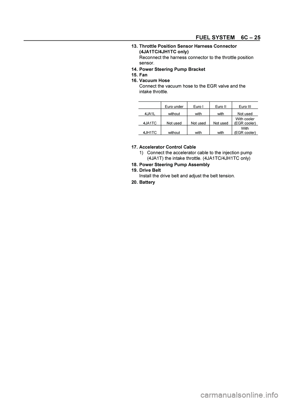
13. Throttle Position Sensor Harness Connector
(4JA1TC/4JH1TC only)
Reconnect the harness connector to the throttle position
sensor.
14. Power Steering Pump Bracket
15. Fan
16. Vacuum Hose
Connect the vacuum hose to the EGR valve and the
intake throttle.
Euro under Euro I Euro II Euro III
4JA1L without with with Not used
4JA1TC Not used Not used Not used With cooler
(EGR cooler)
4JH1TC without with with With
(EGR cooler)
17. Accelerator Control Cable
1) Connect the accelerator cable to the injection pump
(4JA1T) the intake throttle. (4JA1TC/4JH1TC only)
18. Power Steering Pump Assembly
19. Drive Belt
Install the drive belt and adjust the belt tension.
20. Battery
Page 1338 of 4264
6C – 38 FUEL SYSTEM
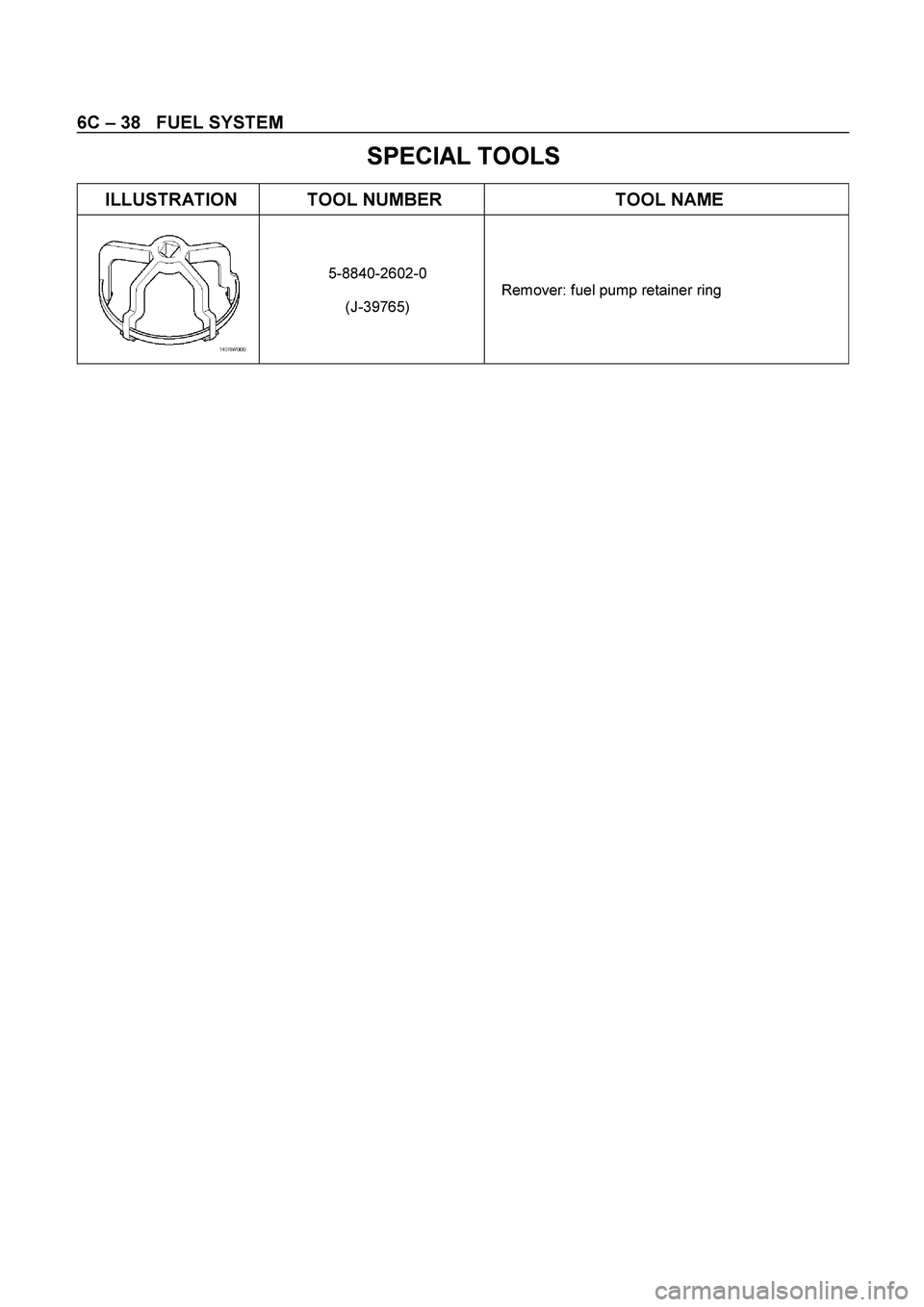
SPECIAL TOOLS
ILLUSTRATION TOOL NUMBER TOOL NAME
5-8840-2602-0
(J-39765) Remover: fuel pump retainer ring
Page 1373 of 4264
4JA1/4JH1 ENGINE DRIVEABILITY AND EMISSIONS 6E–1
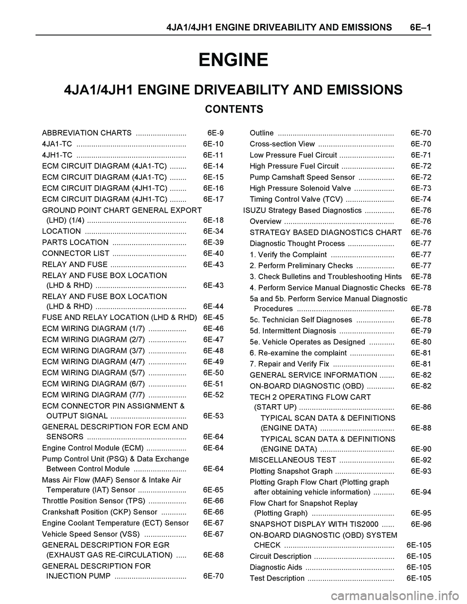
ENGINE
CONTENTS
4JA1/4JH1 ENGINE DRIVEABILITY AND EMISSIONS
ABBREVIATION CHARTS ........................ 6E-9
4JA1-TC .................................................... 6E-10
4JH1-TC .................................................... 6E-11
ECM CIRCUIT DIAGRAM (4JA1-TC) ........ 6E-14
ECM CIRCUIT DIAGRAM (4JA1-TC) ........ 6E-15
ECM CIRCUIT DIAGRAM (4JH1-TC) ........ 6E-16
ECM CIRCUIT DIAGRAM (4JH1-TC) ........ 6E-17
GROUND POINT CHART GENERAL EXPORT
(LHD) (1/4) ............................................... 6E-18
LOCATION ................................................ 6E-34
PARTS LOCATION ................................... 6E-39
CONNECTOR LIST ................................... 6E-40
RELAY AND FUSE .................................... 6E-43
RELAY AND FUSE BOX LOCATION
(LHD & RHD) ........................................... 6E-43
RELAY AND FUSE BOX LOCATION
(LHD & RHD) ........................................... 6E-44
FUSE AND RELAY LOCATION (LHD & RHD) 6E-45
ECM WIRING DIAGRAM (1/7) .................. 6E-46
ECM WIRING DIAGRAM (2/7) .................. 6E-47
ECM WIRING DIAGRAM (3/7) .................. 6E-48
ECM WIRING DIAGRAM (4/7) .................. 6E-49
ECM WIRING DIAGRAM (5/7) .................. 6E-50
ECM WIRING DIAGRAM (6/7) .................. 6E-51
ECM WIRING DIAGRAM (7/7) .................. 6E-52
ECM CONNECTOR PIN ASSIGNMENT &
OUTPUT SIGNAL .................................... 6E-53
GENERAL DESCRIPTION FOR ECM AND
SENSORS ............................................... 6E-64
Engine Control Module (ECM) ................... 6E-64
Pump Control Unit (PSG) & Data Ex change
Between Control Module ......................... 6E-64
Mass Air Flow (MAF) Sensor & Intake Air
Temperature (IAT) Sensor ....................... 6E-65
Throttle Position Sensor (TPS) .................. 6E-66
Crankshaft Position (CKP) Sensor ............ 6E-66
Engine Coolant Temperature (ECT) Sensor 6E-67
Vehicle Speed Sensor (VSS) .................... 6E-67
GENERAL DESCRIPTION FOR EGR
(EXHAUST GAS RE-CIRCULATION) ..... 6E-68
GENERAL DESCRIPTION FOR
INJECTION PUMP .................................. 6E-70Outline ....................................................... 6E-70
Cross-section View .................................... 6E-70
Low Pressure Fuel Circuit .......................... 6E-71
High Pressure Fuel Circuit ......................... 6E-72
Pump Camshaft Speed Sensor ................. 6E-72
High Pressure Solenoid Valve ................... 6E-73
Timing Control Valve (TCV) ....................... 6E-74
ISUZU Strategy Based Diagnostics .............. 6E-76
Overview .................................................... 6E-76
STRATEGY BASED DIAGNOSTICS CHART 6E-76
Diagnostic Thought Process ...................... 6E-77
1. Verify the Complaint .............................. 6E-77
2. Perform Preliminary Checks .................. 6E-77
3. Check Bulletins and Troubleshooting Hints 6E-78
4. Perform Service Manual Diagnostic Checks 6E-78
5a and 5b. Perform Service Manual Diagnostic
Procedures .............................................. 6E-78
5c. Technician Self Diagnoses .................. 6E-78
5d. Intermittent Diagnosis .......................... 6E-79
5e. Vehicle Operates as Designed ............ 6E-80
6. Re-examine the complaint ..................... 6E-81
7. Repair and Verify Fix ............................. 6E-81
GENERAL SERVICE INFORMATION ....... 6E-82
ON-BOARD DIAGNOSTIC (OBD) ............. 6E-82
TECH 2 OPERATING FLOW CART
(START UP) ............................................. 6E-86
TYPICAL SCAN DATA & DEFINITIONS
(ENGINE DATA) ................................... 6E-88
TYPICAL SCAN DATA & DEFINITIONS
(ENGINE DATA) ................................... 6E-90
MISCELLANEOUS TEST .......................... 6E-92
Plotting Snapshot Graph ............................ 6E-93
Plotting Graph Flow Chart (Plotting graph
after obtaining vehicle information) .......... 6E-94
Flow Chart for Snapshot Replay
(Plotting Graph) ....................................... 6E-95
SNAPSHOT DISPLAY WITH TIS2000 ...... 6E-96
ON-BOARD DIAGNOSTIC (OBD) SYSTEM
CHECK .................................................... 6E-105
Circuit Description ...................................... 6E-105
Diagnostic Aids .......................................... 6E-105
Test Description ......................................... 6E-105
Page 1375 of 4264
4JA1/4JH1 ENGINE DRIVEABILITY AND EMISSIONS 6E–3
(Symptom Code 2) (Flash Code 14) Engine
Coolant Temperature Sensor Circuit
LowInput .................................................. 6E-165
DIAGNOSTIC TROUBLE CODE (DTC) P0180
(SYMPTOM CODE B) (FLASH CODE 15)
FUEL TEMPERATURE SENSOR CIRCUIT
RANGE/PERFORMANCE ....................... 6E-168
Circuit Description ..................................... 6E-168
Diagnostic Aids .......................................... 6E-168
Diagnostic Trouble Code (DTC) P0180
(Symptom Code B) (Flash Code 15) Fuel
Temperature Sensor Circuit
Range/Performance ................................ 6E-169
DIAGNOSTIC TROUBLE CODE (DTC) P0215
(SYMPTOM CODE A) (FLASH CODE 52)
FUEL CUTOFF SOLENOID VALVE
MALFUNCTION ....................................... 6E-170
DIAGNOSTIC TROUBLE CODE (DTC) P0215
(SYMPTOM CODE B) (FLASH CODE 52)
FUEL CUTOFF SOLENOID VALVE
CIRCUIT HIGH INPUT ............................ 6E-170
DIAGNOSTIC TROUBLE CODE (DTC) P0215
(SYMPTOM CODE C) (FLASH CODE 52)
FUEL CUTOFF SOLENOID VALVE ALWAYS
ACTIVE .................................................... 6E-170
DIAGNOSTIC TROUBLE CODE (DTC) P0215
(SYMPTOM CODE D) (FLASH CODE 52)
FUEL CUTOFF SOLENOID VALVE
MALFUNCTION ....................................... 6E-170
Circuit Description ..................................... 6E-171
Diagnostic Aids .......................................... 6E-171
Diagnostic Trouble Code (DTC) P0215
(Symptom Code A) (Flash Code 52) Fuel
Cutoff Solenoid Valve Malfunction ........... 6E-171
Diagnostic Trouble Code (DTC) P0215
(Symptom Code B) (Flash Code 52) Fuel
Cutoff Solenoid Valve Circuit High Input . 6E-173
Diagnostic Trouble Code (DTC) P0215
(Symptom Code C) (Flash Code 52) Fuel
Cutoff Solenoid Valve Always Active ....... 6E-175
Diagnostic Trouble Code (DTC) P0215
(Symptom Code D) (Flash Code 52) Fuel
Cutoff Solenoid Valve Malfunction ........... 6E-177
DIAGNOSTIC TROUBLE CODE (DTC) P0216
(SYMPTOM CODE A) (FLASH CODE 54)
INJECTION TIMING CONTROL CIRCUIT
MALFUNCTION ....................................... 6E-178
DIAGNOSTIC TROUBLE CODE (DTC) P0216
(SYMPTOM CODE B) (FLASH CODE 54)
INJECTION TIMING CONTROL CIRCUIT
MALFUNCTION ....................................... 6E-178
Circuit Description ..................................... 6E-179
Diagnostic Aids .......................................... 6E-179Diagnostic Trouble Code (DTC) P0216
(Symptom Code A) (Flash Code 54) Injection
Timing Control Circuit Malfunction ........... 6E-180
Diagnostic Trouble Code (DTC) P0216
(Symptom Code B) (Flash Code 54) Injection
Timing Control Circuit Malfunction ........... 6E-180
DIAGNOSTIC TROUBLE CODE (DTC) P0243
(SYMPTOM CODE 3) (FLASH CODE 64)
TURBOCHARGER WASTEGATE
SOLENOID "A" RANGE/PERFORMANCE 6E-183
DIAGNOSTIC TROUBLE CODE (DTC) P0243
(SYMPTOM CODE 4) (FLASH CODE 64)
TURBOCHARGER WASTEGATE
SOLENOID"A" LOW ................................ 6E-183
DIAGNOSTIC TROUBLE CODE (DTC) P0243
(SYMPTOM CODE 4) (FLASH CODE 64)
TURBOCHARGER WASTEGATE
SOLENOID "A" LOW ............................... 6E-183
DIAGNOSTIC TROUBLE CODE (DTC) P0243
(SYMPTOM CODE 5) (FLASH CODE 64)
TURBOCHARGER WASTEGATE
SOLENOID "A" RANGE/PERFORMANCE 6E-183
DIAGNOSTIC TROUBLE CODE (DTC) P0243
(SYMPTOM CODE 6) (FLASH CODE 64)
TURBOCHARGER WASTEGATE
SOLENOID "A" MALFUNCTION ............. 6E-183
DIAGNOSTIC TROUBLE CODE (DTC) P0243
(SYMPTOM CODE 8) (FLASH CODE 64)
TURBOCHARGER WASTEGATE
SOLENOID"A" HIGH ............................... 6E-183
Circuit description ...................................... 6E-184
Diagnostic Aids .......................................... 6E-184
Diagnostic Trouble Code (DTC) P0243
(Symptom Code 3) (Flash Ccode 64)
Turbocharger Wastegate Solenoid
"A" Range/Performance ........................... 6E-185
Diagnostic Trouble Code (DTC) P0243
(Symptom Code 4) (Flash Code 64)
Turbocharger Wastegate Solenoid "A" Low 6E-187
Diagnostic Trouble Code (DTC) P0243
(Symptom Code 5) (Flash Code 64)
Turbocharger Wastegate Solenoid "A"
Range/Performance ................................ 6E-190
Diagnostic Trouble Code (DTC) P0243
(Symptom Code 6) (Flash Code 64)
Turbocharger Wastegate Solenoid "A"
Malfunction .............................................. 6E-192
Diagnostic Trouble Code (DTC) P0243
(Symptom Code 8) (Flash Code 64)
Turbocharger Wastegate Solenoid "A" High 6E-194
DIAGNOSTIC TROUBLE CODE (DTC) P0251
(SYMPTOM CODE 6)
(FLASH CODE 53) INJECTION PUMP
Page 1384 of 4264
6E–12 4JA1/4JH1 ENGINE DRIVEABILITY AND EMISSIONS
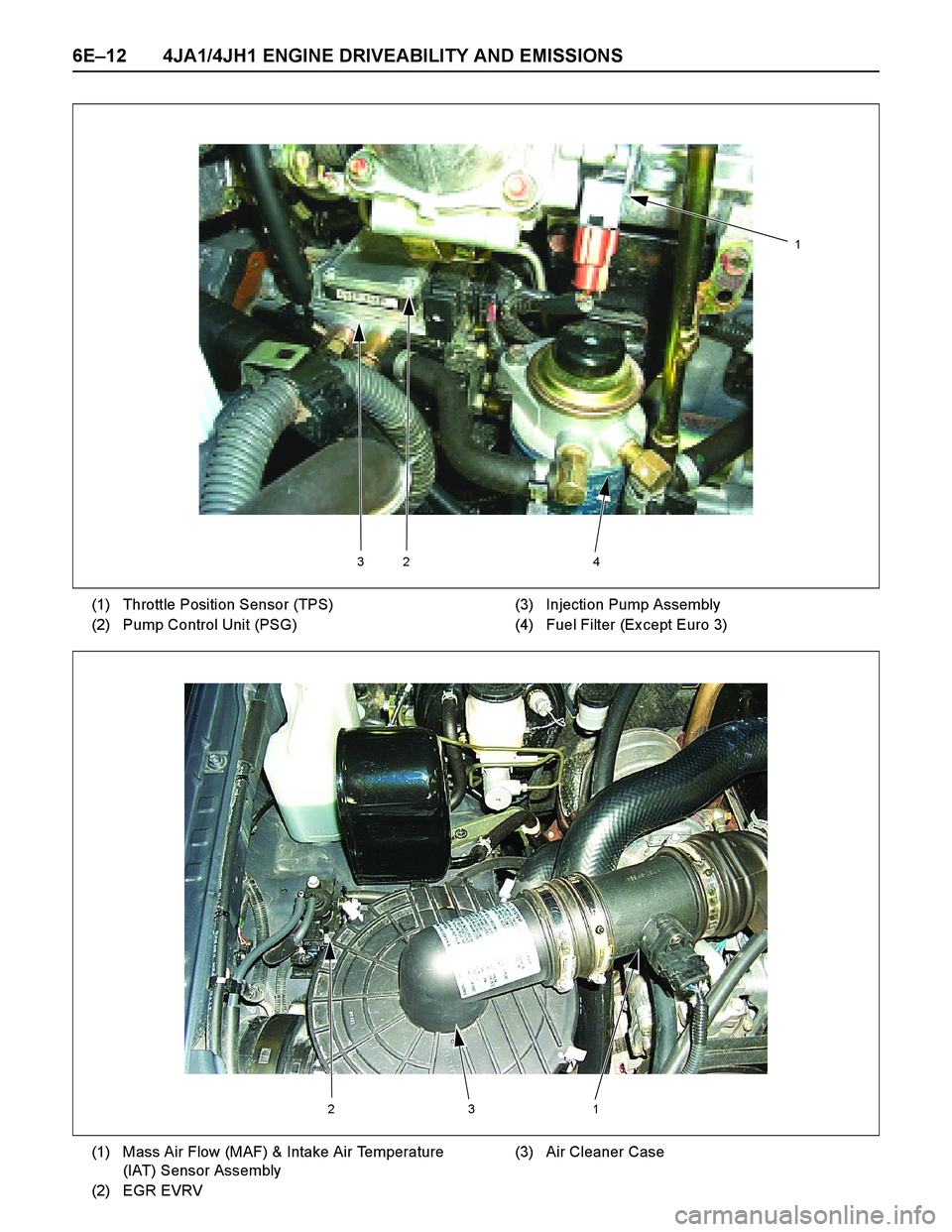
324
1
(1) Throttle Position Sensor (TPS)
(2) Pump Control Unit (PSG)(3) Injection Pump Assembly
(4) Fuel Filter (Ex cept Euro 3)
213
(1) Mass Air Flow (MAF) & Intake Air Temperature
(IAT) Sensor Assembly
(2) EGR EVRV(3) Air Cleaner Case
Page 1436 of 4264
6E–64 4JA1/4JH1 ENGINE DRIVEABILITY AND EMISSIONS
GENERAL DESCRIPTION FOR ECM AND
SENSORS
Engine Control Module (ECM)
The engine control module (ECM) is located flower
panel just under the passenger's seat.
The fuel quantity and injection timing related functions
are controlled by the pump control unit (PSG).
The engine control module (ECM) performs the
following functions.
Control of the ex haust gas re-circulation (EGR)
Control of the quick on start (QOS) glow control
system
Control of the A/C compressor
Ex ecution of the immobilizer function
Pump Control Unit (PSG) & Data Exchange
Between Control Module
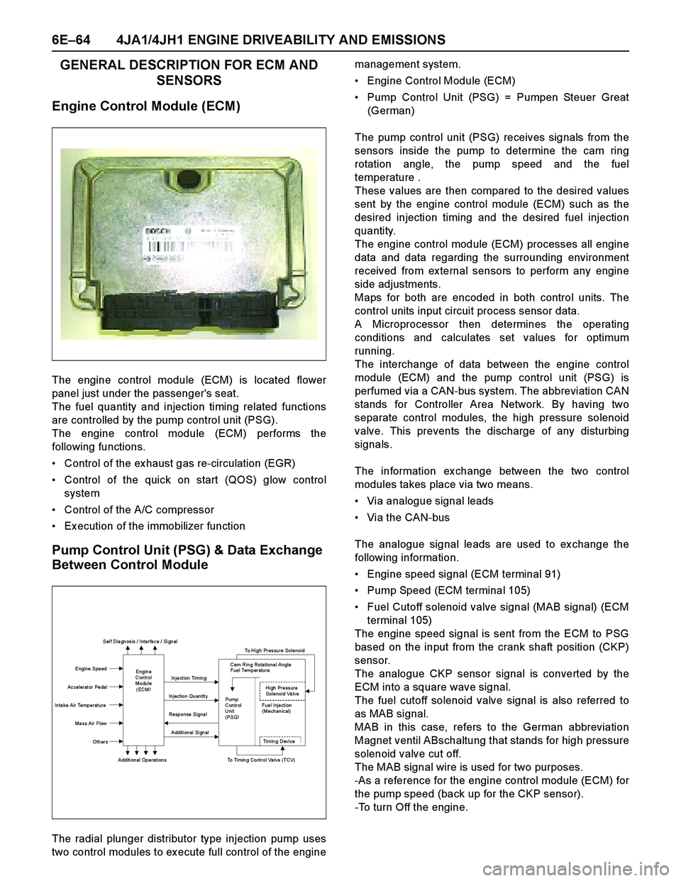
The radial plunger distributor type injection pump uses
two control modules to ex ecute full control of the enginemanagement system.
Engine Control Module (ECM)
Pump Control Unit (PSG) = Pumpen Steuer Great
(German)
The pump control unit (PSG) receives signals from the
sensors inside the pump to determine the cam ring
rotation angle, the pump speed and the fuel
temperature .
These values are then compared to the desired values
sent by the engine control module (ECM) such as the
desired injection timing and the desired fuel injection
quantity.
The engine control module (ECM) processes all engine
data and data regarding the surrounding environment
received from ex ternal sensors to perform any engine
side adjustments.
Maps for both are encoded in both control units. The
control units input circuit process sensor data.
A Microprocessor then determines the operating
conditions and calculates set values for optimum
running.
The interchange of data between the engine control
module (ECM) and the pump control unit (PSG) is
perfumed via a CAN-bus system. The abbreviation CAN
stands for Controller Area Network. By having two
separate control modules, the high pressure solenoid
valve. This prevents the discharge of any disturbing
signals.
The information ex change between the two control
modules takes place via two means.
Via analogue signal leads
Via the CAN-bus
The analogue signal leads are used to ex change the
following information.
Engine speed signal (ECM terminal 91)
Pump Speed (ECM terminal 105)
Fuel Cutoff solenoid valve signal (MAB signal) (ECM
terminal 105)
The engine speed signal is sent from the ECM to PSG
based on the input from the crank shaft position (CKP)
sensor.
The analogue CKP sensor signal is converted by the
ECM into a square wave signal.
The fuel cutoff solenoid valve signal is also referred to
as MAB signal.
MAB in this case, refers to the German abbreviation
Magnet ventil ABschaltung that stands for high pressure
solenoid v alv e cut off.
The MAB signal wire is used for two purposes.
-As a reference for the engine control module (ECM) for
the pump speed (back up for the CKP sensor).
-To turn Off the engine.
Sel f Dia gn osis / Interfa ce / Si gn al
To High Pressure Solenoid
Engine Speed
Injection Timing
Accelerator Pedal
Injection Quantity
In ta ke Air Temperat ure
Response Signal
Ma ss Air Flow
Additional Signal
Others
Additional Operations To Timing Control Valve (TCV)
Engin e
Con trol
Modu le
(ECM) Cam Rin g Rota tiona l Angle
Fuel Temper atu re
High Pressure
Solenoid Valve
Pump
Con tr ol Fuel Inject ion
Unit (Mechanical)
(PSG)
Ti m i n
g Devi ce
Page 1437 of 4264
4JA1/4JH1 ENGINE DRIVEABILITY AND EMISSIONS 6E–65
The following signals are ex changed via the CAN-bus:
From ECM to PSG
Desired injection quantity
Desired injection timing
Engine speed
From PSG to ECM
Fuel temperature
Pump speed
Cylinder identifier
Control pulse (actual injection quantity + actual
injection timing)
PSG status
Mass Air Flow (MAF) Sensor & Intake Air
Temperature (IAT) Sensor
The mass air flow (MAF) sensor is part of the intake air
system.
It is fitted between the air cleaner and turbocharger and
measure the mass air flowing into the engine.
The mass air flow (MAF) sensor uses a hot film element
to determine the amount of air flowing into the engine.
The mass air flow (MAF) sensor assembly consist of a
mass air flow (MAF) sensor element and an intake air
temperature sensor that are both ex posed to the air flow
to be measured.
The mass air flow (MAF) sensor element measures the
partial air mass through a measurement duct on the
sensor housing.
Using calibration, there is an ex trapolation to the entire
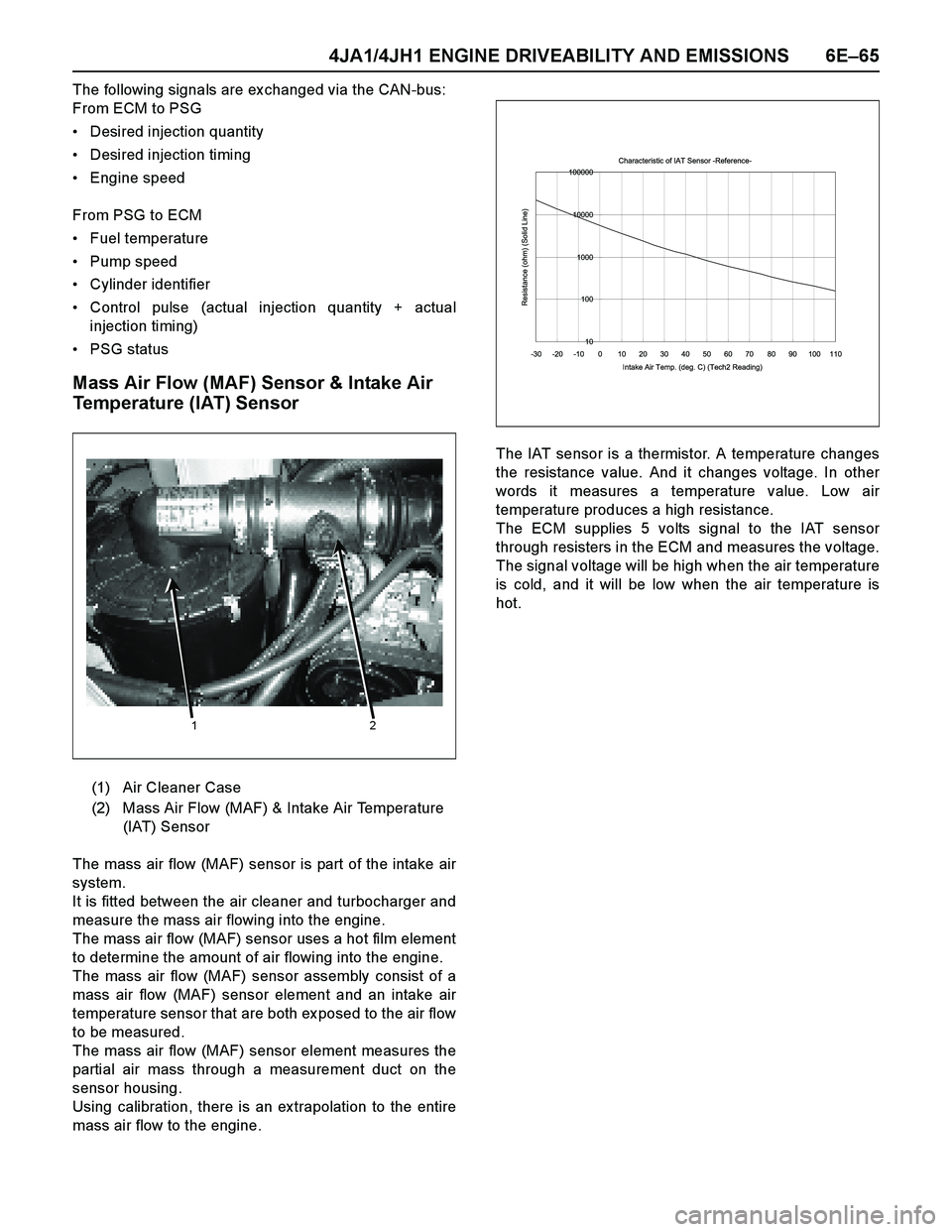
mass air flow to the engine.The IAT sensor is a thermistor. A temperature changes
the resistance value. And it changes voltage. In other
words it measures a temperature value. Low air
temperature produces a high resistance.
The ECM supplies 5 volts signal to the IAT sensor
through resisters in the ECM and measures the voltage.
The signal voltage will be high when the air temperature
is cold, and it will be low when the air temperature is
hot.
(1) Air Cleaner Case
(2) Mass Air Flow (MAF) & Intake Air Temperature
(IAT) Sensor
1 2
Characteristic of IAT Sensor -Reference-
10 100 1000 10000 100000
-30 -20 -10 0 10 20 30 40 50 60 70 80 90 100 110
Intake Air Temp. (deg. C) (Tech2 Reading)
Resistance (ohm) (Solid Line)