Page 1144 of 4264
6A – 4 ENGINE MECHANICAL
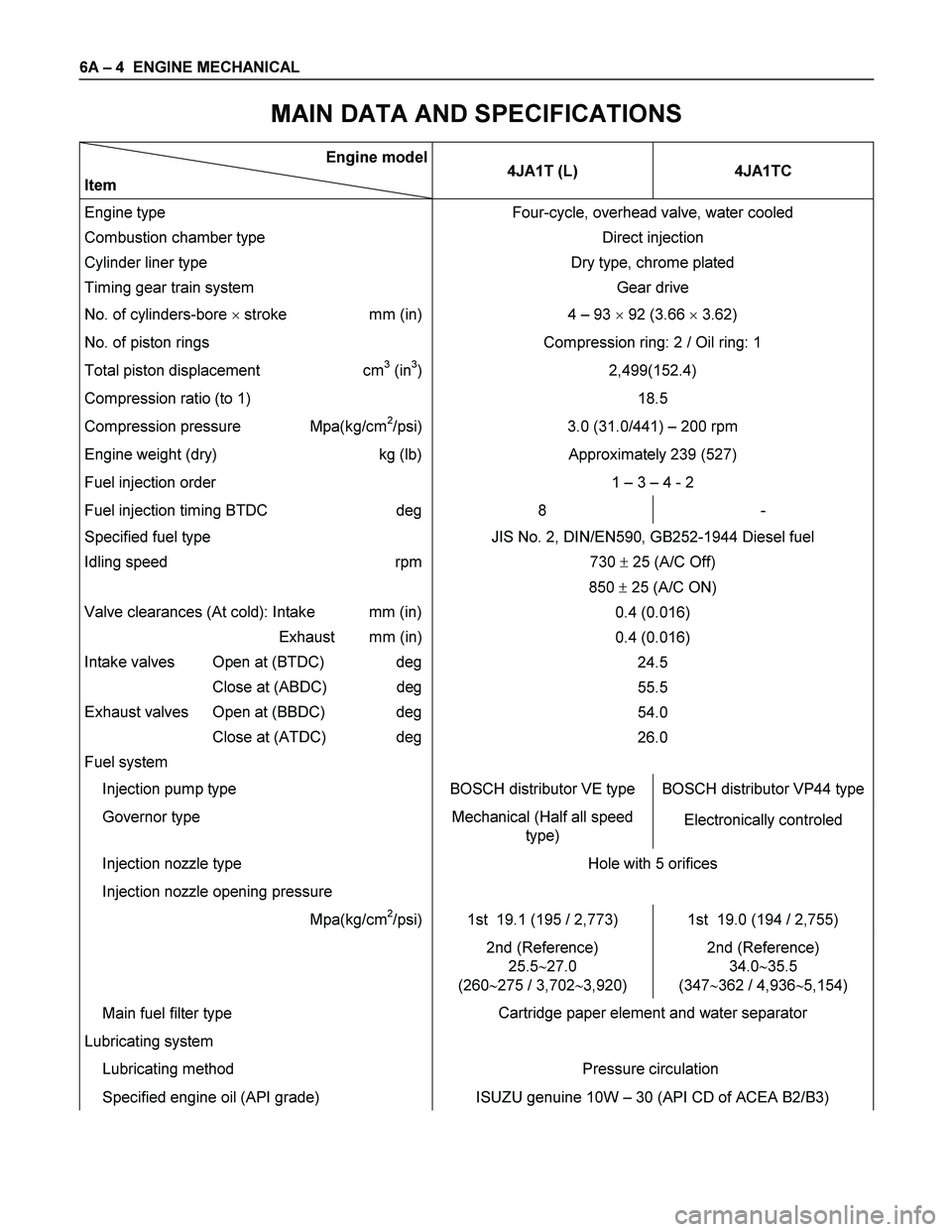
MAIN DATA AND SPECIFICATIONS
Engine model
Item 4JA1T (L) 4JA1TC
Engine type
Combustion chamber type
Cylinder liner type
Timing gear train system Four-cycle, overhead valve, water cooled
Direct injection
Dry type, chrome plated
Gear drive
No. of cylinders-bore � stroke mm (in) 4 – 93 � 92 (3.66 � 3.62)
No. of piston rings Compression ring: 2 / Oil ring: 1
Total piston displacement cm3 (in3)
Compression ratio (to 1) 2,499(152.4)
18.5
Compression pressure Mpa(kg/cm2/psi) 3.0 (31.0/441) – 200 rpm
Engine weight (dry) kg (lb) Approximately 239 (527)
Fuel injection order 1 – 3 – 4 - 2
Fuel injection timing BTDC deg 8 -
Specified fuel type
Idling speed rpm
Valve clearances (At cold): Intake mm (in)
Exhaust mm (in)
Intake valves Open at (BTDC) deg
Close at (ABDC) deg
Exhaust valves Open at (BBDC) deg
Close at (ATDC) deg
Fuel system JIS No. 2, DIN/EN590, GB252-1944 Diesel fuel
730 � 25 (A/C Off)
850 � 25 (A/C ON)
0.4 (0.016)
0.4 (0.016)
24.5
55.5
54.0
26.0
Injection pump type BOSCH distributor VE type BOSCH distributor VP44 type
Governor type Mechanical (Half all speed
type) Electronically controled
Injection nozzle type
Injection nozzle opening pressure Hole with 5 orifices
Mpa(kg/cm2/psi) 1st 19.1 (195 / 2,773) 1st 19.0 (194 / 2,755)
2nd (Reference)
25.5�27.0
(260�275 / 3,702�3,920) 2nd (Reference)
34.0�35.5
(347�362 / 4,936�5,154)
Main fuel filter type
Lubricating system
Lubricating method Cartridge paper element and water separator
Pressure circulation
Specified engine oil (API grade) ISUZU genuine 10W – 30 (API CD of ACEA B2/B3)
Page 1146 of 4264
6A – 6 ENGINE MECHANICAL
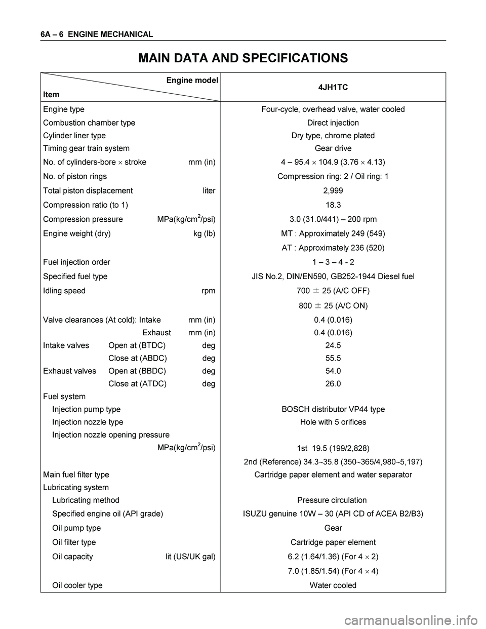
MAIN DATA AND SPECIFICATIONS
Engine model
Item 4JH1TC
Engine type Four-cycle, overhead valve, water cooled
Combustion chamber type Direct injection
Cylinder liner type
Timing gear train system Dry type, chrome plated
Gear drive
No. of cylinders-bore � stroke mm (in) 4 – 95.4 � 104.9 (3.76 � 4.13)
No. of piston rings Compression ring: 2 / Oil ring: 1
Total piston displacement liter
Compression ratio (to 1) 2,999
18.3
Compression pressure MPa(kg/cm2/psi) 3.0 (31.0/441) – 200 rpm
Engine weight (dry) kg (lb) MT : Approximately 249 (549)
AT : Approximately 236 (520)
Fuel injection order 1 – 3 – 4 - 2
Specified fuel type JIS No.2, DIN/EN590, GB252-1944 Diesel fuel
Idling speed rpm
700 � 25 (A/C OFF)
800 � 25 (A/C ON)
Valve clearances (At cold): Intake mm (in)
Exhaust mm (in)
Intake valves Open at (BTDC) deg
Close at (ABDC) deg
Exhaust valves Open at (BBDC) deg
Close at (ATDC) deg
Fuel system
Injection pump type 0.4 (0.016)
0.4 (0.016)
24.5
55.5
54.0
26.0
BOSCH distributor VP44 type
Injection nozzle type
Injection nozzle opening pressure
MPa(kg/cm
2/psi)Hole with 5 orifices
1st 19.5 (199/2,828)
2nd (Reference) 34.3�35.8 (350�365/4,980�5,197)
Main fuel filter type
Lubricating system
Lubricating method Cartridge paper element and water separator
Pressure circulation
Specified engine oil (API grade) ISUZU genuine 10W – 30 (API CD of ACEA B2/B3)
Oil pump type
Oil filter type Gear
Cartridge paper element
Oil capacity lit (US/UK gal)
6.2 (1.64/1.36) (For 4 � 2)
7.0 (1.85/1.54) (For 4 � 4)
Oil cooler type Water cooled
Page 1165 of 4264
ENGINE MECHANICAL 6A – 25
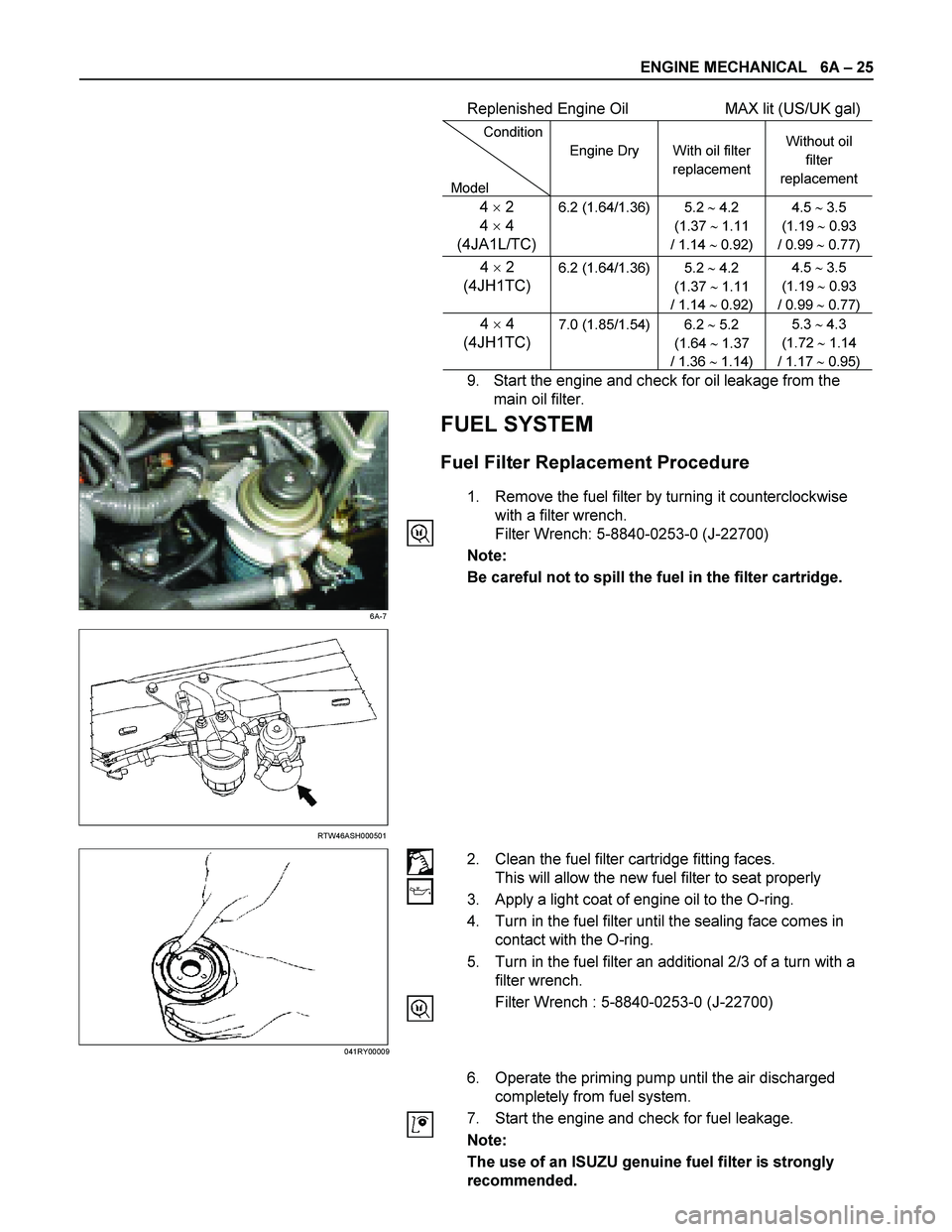
Replenished Engine Oil MAX lit (US/UK gal)
Condition
Model Engine Dry
With oil filter
replacement Without oil
filter
replacement
4 � 2
4 � 4
(4JA1L/TC)6.2 (1.64/1.36) 5.2 � 4.2
(1.37 � 1.11
/ 1.14 � 0.92) 4.5 � 3.5
(1.19 � 0.93
/ 0.99 � 0.77)
4 � 2
(4JH1TC)
6.2 (1.64/1.36) 5.2 � 4.2
(1.37 � 1.11
/ 1.14 � 0.92) 4.5 � 3.5
(1.19 � 0.93
/ 0.99 � 0.77)
4 � 4
(4JH1TC) 7.0 (1.85/1.54) 6.2 � 5.2
(1.64 � 1.37
/ 1.36 � 1.14) 5.3 � 4.3
(1.72 � 1.14
/ 1.17 � 0.95)
9. Start the engine and check for oil leakage from the
main oil filter.
6A-7
FUEL SYSTEM
Fuel Filter Replacement Procedure
1. Remove the fuel filter by turning it counterclockwise
with a filter wrench.
Filter Wrench: 5-8840-0253-0 (J-22700)
Note:
Be careful not to spill the fuel in the filter cartridge.
RTW46ASH000501
2. Clean the fuel filter cartridge fitting faces.
This will allow the new fuel filter to seat properly
3. Apply a light coat of engine oil to the O-ring.
4. Turn in the fuel filter until the sealing face comes in
contact with the O-ring.
5. Turn in the fuel filter an additional 2/3 of a turn with a
filter wrench.
Filter Wrench : 5-8840-0253-0 (J-22700)
6. Operate the priming pump until the air discharged
completely from fuel system.
7. Start the engine and check for fuel leakage.
Note:
The use of an ISUZU genuine fuel filter is strongly
recommended.
041RY00009
Page 1166 of 4264
6A – 26 ENGINE MECHANICAL
041RY00011
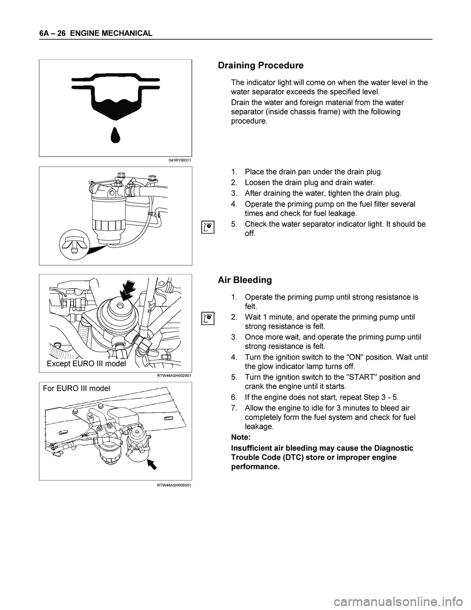
Draining Procedure
The indicator light will come on when the water level in the
water separator exceeds the specified level.
Drain the water and foreign material from the water
separator (inside chassis frame) with the following
procedure.
1. Place the drain pan under the drain plug.
2. Loosen the drain plug and drain water.
3. After draining the water, tighten the drain plug.
4. Operate the priming pump on the fuel filter several
times and check for fuel leakage.
5. Check the water separator indicator light. It should be
off.
Except EURO III model
RTW46ASH002901
For EURO III model
RTW46ASH000501
Air Bleeding
1. Operate the priming pump until strong resistance is
felt.
2. Wait 1 minute, and operate the priming pump until
strong resistance is felt.
3. Once more wait, and operate the priming pump until
strong resistance is felt.
4. Turn the ignition switch to the "ON" position. Wait until
the glow indicator lamp turns off.
5. Turn the ignition switch to the "START" position and
crank the engine until it starts.
6. If the engine does not start, repeat Step 3 - 5.
7. Allow the engine to idle for 3 minutes to bleed air
completely form the fuel system and check for fuel
leakage.
Note:
Insufficient air bleeding may cause the Diagnostic
Trouble Code (DTC) store or improper engine
performance.
Page 1176 of 4264
6A – 36 ENGINE MECHANICAL
GENERAL DESCRIPTION
RTW46AMF000401
The 4J series automotive diesel engine has special designed combustion chambers in the piston. This design
provides superior fuel economy over a wide range of driving conditions.
Auto-thermatic pistons with cast steel struts are used to reduce thermal expansion and resulting engine noise when
the engine is cold.
Chrome plated dry type cylinder liners provide the highest durability.
The laminated steel sheet cylinder head gasket is very durable and, to increase the head gasket reliability.
The crankshaft has been tufftrided to provide a longer service life. Because the crankshaft is tufftrided, it cannot be
reground.
The 4JA1T(L) engine is equipped with the BOSCH VE-Type distributor injection pump.
The 4JH1TC and 4JA1TC engine is equipped with the BOSCH VP44-Type distributor injection pump.
The engine is turbocharger equipped.
Page 1180 of 4264
6A – 40 ENGINE MECHANICAL
140R300001
26. Fuel Hose
Remove the fuel hose from the fuel filter (Except EURO
III).
RTW46ASH000501
Remove the fuel hose from injection pump (EURO III
only).
27. Exhaust Pipe
Remove the front exhaust pipe bolts and separate the
exhaust manifold and the front exhaust pipe.
28. Engine Assembly
1) Remove two right side engine foot bolts.
2) Remove two left side engine mount bolts.
3) Use the hoist to lift the engine from the engine
compartment.
Installation
To reassemble, follow the removal steps in the reverse
order.
022R300002
F06R300008
Page 1183 of 4264
ENGINE MECHANICAL 6A – 43
ENGINE OVERHAUL
REMOVAL
EXTERNAL PARTS
RTW36AMF000401
Removal Steps
1. Clutch Assembly or Flex Plate
2. Intake Pipe and Throttle Body
3-1. EGR Pipe
3-2. EGR cooler (EURO III model only)
4. EGR Valve
5. Oil Level Gauge
6. Fuel Filter Assembly (Except EURO III)
7. Fuel Filter Bracket (Except EURO III)
8. Fuel Injection Pipe with Clip
9. Power Steering Oil Pump Bracket
10. Intake Manifold
11. Engine Mounting Bracket and Foot
12. Injection Pump Cover
13. Injection Pump
14. Starter Motor
15. Oil Pressure Warning Switch
16. Fuel Leak Off Pipe
17. Oil Cooler Water Pipe
18. Cooling Fan Pulley
19. Heat Protector
20. Catalytic Converter
21. Turbocharger
22. Compressor Bracket
23. Vacuum Pump Oil Return Hose
24. Generator and Adjusting Plate
25. Water Inlet Pipe
26. Generator Bracket
27. Oil Cooler with Oil Filter
28. Exhaust Manifold
Page 1185 of 4264
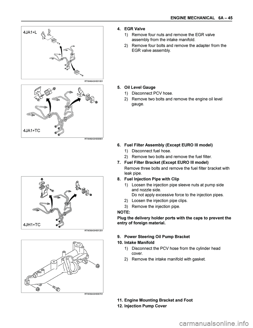
ENGINE MECHANICAL 6A – 45
4JA1�L
RTW46ASH001001
4. EGR Valve
1) Remove four nuts and remove the EGR valve
assembly from the intake manifold.
2) Remove four bolts and remove the adapter from the
EGR valve assembly.
4JA1�TC RTW46ASH000901
5. Oil Level Gauge
1) Disconnect PCV hose.
2) Remove two bolts and remove the engine oil level
gauge.
6. Fuel Filter Assembly (Except EURO III model)
1) Disconnect fuel hose.
2) Remove two bolts and remove the fuel filter.
7. Fuel Filter Bracket (Except EURO III model)
Remove three bolts and remove the fuel filter bracket with
leak pipe.
4JH1�TC RTW36ASH001201
8. Fuel Injection Pipe with Clip
1) Loosen the injection pipe sleeve nuts at pump side
and nozzle side.
Do not apply excessive force to the injection pipes.
2) Loosen the injection pipe clips.
3) Remove the injection pipe.
NOTE:
Plug the delivery holder ports with the caps to prevent the
entry of foreign material.
9. Power Steering Oil Pump Bracket
RTW36ASH000701
10. Intake Manifold
1) Disconnect the PCV hose from the cylinder head
cover.
2) Remove the intake manifold with gasket.
11. Engine Mounting Bracket and Foot
12. Injection Pump Cover