Page 1089 of 4264
ELECTRICAL-BODY AND CHASSIS 8A-431
No. Connector face No. Connector face
E-71
NOT USED E-80
(6VE1)
Cylinder revolution
E-72
(C24SE)
(6VE1)
Engine earth-A E-81
(6VE1)
Speed sensor
E-73
(6VE1)
Engine earth-A E-82
(6VE1)
Transmission wire
E-74
(C24SE)
(6VE1)
Engine earth-B E-83
(6VE1)
Oil temperature sensor
E-75
(C24SE)
(6VE1)
Oil pressure switch E-84
(C24SE)
Knock sensor
E-76
(6VE1)
EGR valve E-85
(C24SE)
MAP sensor
E-77
(C24SE)
O2 sensor E-86
(4JA1-L)
SilverThermo switch; QOS
E-77
(6VE1)
O2 sensor RH-Front E-87
(4JA1-L)
WhiteSolenoid CSD
E-78
(6VE1)
O2 sensor LH-Front E-88
(4JA1-L)
SilverThermo switch; EGR
E-79
(6VE1)
Neutral start switch E-89
(4JA1-L)
White
Immobilizer engine control unit
Page 1107 of 4264
.
� Disconnect the connector (3).
� Remove the cable end (1) f")
CRUISE CONTROL SYSTEM 8B-9
RTW3A0SH001001
Removal
1. Disconnect the battery cable.
2. Remove the cruise actuator Assembly (4).
� Disconnect the connector (3).
� Remove the cable end (1) from the throttle link (cruise
control side).
� Loosen a fixing nut of the cruise control cable (2).
� Remove fixing screws of the actuator (5).
Installation
To install, follow the removal steps in the reverse order, noting
the following point.
1. Take care not to bend the cable excessively.
RTW3A0SH001501
Adjustment
After installing the cruise actuator, the following steps must be
carried out for cruise control cable adjustment.
1. Install the cruise control cable end (3) to the throttle link (4).
2. Put the screw portion of the cable in the bracket (5).
3. Put the nut (1) to the bracket and then tighten the nut (2).
CAUTION: Don't move a position of the nut (1) from
supplied condition.
4. If the distance between the throttle link (4) and the throttle
link lever (6) is out of the specified range, loosen the nut (2)
to adjust it.
Mode Switch
Removal and Installation
Refer to the Mode Switch removal and installation steps in
Automatic Transmission section.
Page 1174 of 4264

is aligned with the pointer.
Inj")
6A – 34 ENGINE MECHANICAL
RTW46ASH000701
9. Turn the crankshaft clockwise and read the gauge
indication when the crankshaft pulley timing mark (8�)
is aligned with the pointer.
Injection Timing : BTDC 8� � 2�
Standard Reading mm (in)
0.5 (0.02)
If the injection timing is outside the specified range,
continue with the following steps.
10. Loosen the injection pump fixing nuts and bracket
bolts.
11. Adjust the injection pump setting angle.
When large than standard
value When smaller than standard
value
R A
A: Move the injection pump toward the engine.
R: Move the injection pump away from the engine.
ENGINE CONTROL (4JA1T(L) only)
Idling Speed Adjustment
1. Set the vehicle parking brake and chock the drive
wheels.
2. Place the transmission in neutral.
3. Start the engine and allow it to idle until the coolant
temperature reaches 70 - 80�C (158 - 176�F).
4. Disconnect the engine control cable from the control
lever.
5. Set a tachometer to the engine.
6. Check the engine idling speed.
If the engine idling speed is outside the specified
range, it must be adjusted.
Engine Idling Speed : 730 � 25 rpm
Idling Speed Adjustment
1. Loosen the idling set screw lock nut � on the injection
pump idling set bolt.
2. Adjust the idling speed to the specified range by
turning the idling set bolt
�.
3. Lock the engine set nut
� with the idling set bolt lock
nut.
4. Check that the idling control cable is tight (free of
slack). If required, remove the slack from the cable.
Page 1177 of 4264

ENGINE MECHANICAL 6A – 37
REMOVAL AND INSTALLATION
Read this section carefully before performing any removal and installation procedure. This section gives
you important points as well as the order of operation. Be sure that you understand everything in this section before
you begin.
Removal
P1010011
1. Battery
1) Disconnect the battery cable and the grounding cable from the battery terminals.
2) Remove the battery clamp. Take care not to accidentally short the battery with the wrench or some
other tool.
3) Remove the battery.
4) Disconnect the battery cable at the starter motor and the ground cable at the cylinder body.
2. Engine Hood Apply setting marks to the engine hood and the engine
hood hinges before removing the engine hood. This will
facilitate reinstallation of the engine hood to its original
position.
3. Supporting the Vehicle 1) Jack up the vehicle.
2) Place chassis stands at the front and the rear of the vehicle.
4. Under cover (for 4x4 model) 5. Rear propeller shaft 1) Remove the propeller shaft flange yoke at the rear differential.
2) Remove the center bearing retainer bolts.
3) Remove the propeller shaft together with the center bearing from the transmission mainshaft spline.
F06R300006 P1010002
Page 1178 of 4264

Remove the spline yoke flange bolt at the transfer output
shaft.
Do not allow the spline yoke to fall away from the front")
6A – 38 ENGINE MECHANICAL
6. Front propeller shaft (for 4x4 model)
Remove the spline yoke flange bolt at the transfer output
shaft.
Do not allow the spline yoke to fall away from the front
propeller shaft.
If the spline yoke should fall away from the front propeller
shaft, align the setting marks on the spline yoke and the
propeller shaft to reassemble the two marks. The setting
marks are punched circles approx. 3mm (0.12 in) in
diameter.
7. Clutch slave cylinder (for M/T model)
8. ATF pipe (for A/T model)
9 Shift control cable (for A/T model)
10. Transmission sensor harness
Remove the vehicle speed sensor connector, inhibitor
switch connector (A/T), ATF temperature sensor
connector, back up light switch connector (M/T) from
transmission.
11. Breather hose (for A/T model)
12. Transmission shift lever (for M/T model)
Remove the shift lever from the floor.
13. Transfer shift lever (for 4x4 model)
Remove the shift lever from the floor.
14. Transmission member
1) Support the transmission with the transmission jack.
2) Remove the transmission member mounting bolts
fixing the transmission member to the chassis frame.
15. Torque converter bolt (for A/T model)
1) Remove the under cover under the torque converter
housing.
2) Rotate the flywheel by using tire lever or some other
tool, and then remove the torque converter bolts.
16. Transmission coupling bolt
1) Support the engine with the garage jack.
2) Use the jack to slightly lower the transmission.
3) Remove the transmission coupling bolts.
17. Transmission (and transfer)
Separate the transmission (and transfer) from the
engine.Take care not to damage the transmission, the
engine, and their related parts..
F06R300007 P1010025
Page 1181 of 4264

ENGINE MECHANICAL 6A – 41
Coolant Replenishment
Warning:
When the coolant is heated to a high temperature, be
sure not to loosen or remove the rediator cap.
Otherwise you might get scalded by hot vapor or
boiling water.
To open the radiator cap, put a piece of thick cloth on
the cap and loosen the cap slowly to reduce the
pressure when the coolant has become cooler.
1. Open rediator cap pour coolant up to filler neck
2. Pour coolant into reservoir tank up to "MAX" line
3. Tighten radiator cap and start the engine. After idling
for 2 to 3 minutes, stop the engine and reopen radiator
cap. If the water level is lower, replenish.
4. After replenish the coolant tighten radiator cap, warm
up the engine at about 2000 rpm. Set heater
adjustment to the highest temperature position, and let
the coolant circulate also into heater water system.
5. Check to see the thermometer, continuously idling 5
minutes and stop the engine.
6. When the engine has been cooled, check filler neck for
water level and replenish if required. Should extreme
shortage of coolant is found, check the coolant system
and reservoir tank hose for leakage.
7. Pour coolant into the reservoir tank up to "MAX" line.
Coolant Capacity lit (US/UK gal)
4JA1 / TC 9.4 (2.5 / 2.1)
4JH1TC M/T: 10.1 (2.7 / 2.2)
A/T: 10.0 (2.6 / 2.2)
9.5 (2.5/2.1)
Engine Warm-Up
After completing the required maintenance procedures,
start the engine and allow it to idle until it is warm.
Check the following:
1. Engine idling speed.
2. Engine noise level.
3. Engine lubricating system and cooling system.
Carefully check for oil and coolant leakage.
4. Clutch engagement.
5. Transmission operation.
6. Indicator warning light operation.
Page 1296 of 4264
6B – 16 ENGINE COOLING
P1010064
Removal
1. Disconnect battery ground cable.
2. Loosen a drain plug to drain EC.
3. Disconnect oil cooler hose on automatic transmission (A/T).
4. Disconnect radiator inlet hose and outlet hose from the engine.
PTW46BSH000101
5. Remove fan guide(1), clips(2) on both sides and the bottom
lock, then remove lower fan guide(3) with fan shroud(4).
6. Disconnect the reserve tank hose(6) from radiator.
RTW36BMH000101
7. Remove bracket(5).
8. Lift up and remove the radiator assembly with hose, taking
care not to damage the radiator core with a fan blade.
Page 1298 of 4264
6B – 18 ENGINE COOLING
110RS005
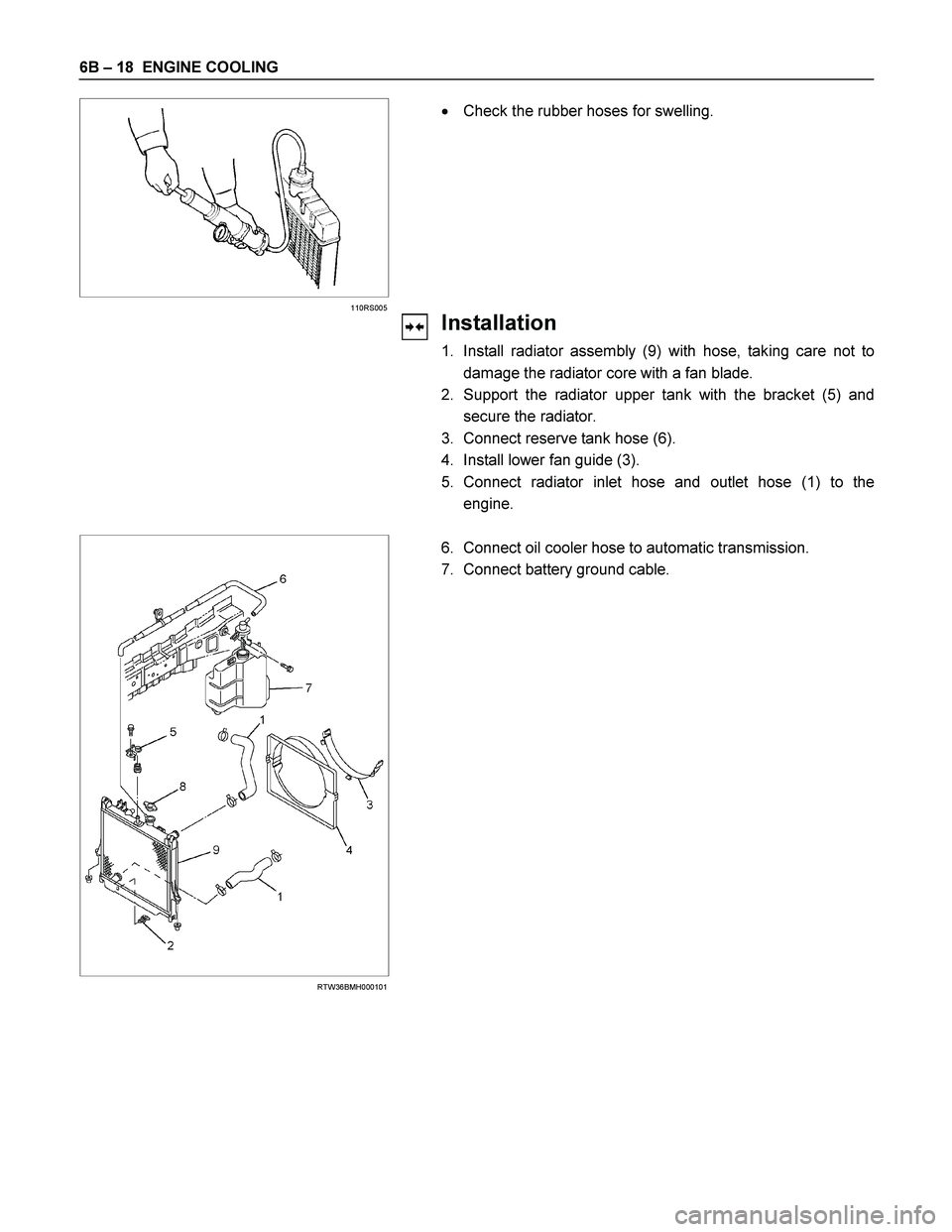
� Check the rubber hoses for swelling.
Installation
1. Install radiator assembly (9) with hose, taking care not to
damage the radiator core with a fan blade.
2. Support the radiator upper tank with the bracket (5) and
secure the radiator.
3. Connect reserve tank hose (6).
4. Install lower fan guide (3).
5. Connect radiator inlet hose and outlet hose (1) to the
engine.
RTW36BMH000101
6. Connect oil cooler hose to automatic transmission.
7. Connect battery ground cable.

Cylinder revolution
E-72
(C24SE)
(6VE1)
Engine earth-A E-81
(6VE1)
Speed senso")
.
4. Discon")