Page 294 of 4264
4C1-74 FRONT WHEEL DRIVE
PROPELLER SHAFT
1. NOISE
Checkpoint Trouble Cause Countermeasure
Spider bearingReplaceWorn or jammed
ReplaceDamaged or worn
NG NG
OKYoke spline
2. VIBRATION
Shaft balanceAdjustUnbalance
ReplaceIncorrect
NG NG
OKShaft runout
Transmission rear housing
bushing, transfer case
housing bushing
ReplaceWorn NG OK
Yoke splineReplaceJammed NG OK
Page 495 of 4264
PARKING BRAKE SYSTEM 5D-5
Front Parking Brake Cable
Front Parking Brake Cable and Associated Parts (Bench Seat)
750R300003
Legend
(1)
Shift Knob (manual transmission)
(2)
Front Floor Console
(3)
Rear Cover
(4)
Bolt
(5)
Seat Assembly
(6)
Buckle: side seat and Center Seat Belt
(7)
Seat Adjuster
Page 623 of 4264
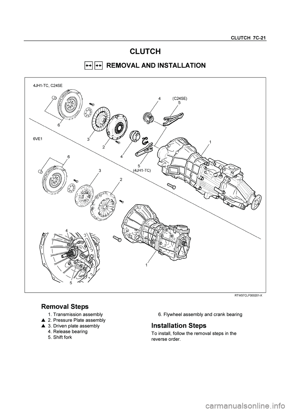
CLUTCH 7C-21
CLUTCH
REMOVAL AND INSTALLATION
RTW37CLF000201-X
Removal Steps
1. Transmission assembly
�
2. Pressure Plate assembly
�
3. Driven plate assembly
4. Release bearing
5. Shift fork
6. Flywheel assembly and crank bearing
Installation Steps
To install, follow the removal steps in the
reverse order.
Page 624 of 4264
7C-22 CLUTCH
Important Operations - Removal
1. Transmission Assembly
Refer to “MANUAL TRANSMISSION” of section 7B and 7B1
for “REMOVAL AND INSTALLATION” procedure.
2. Clutch Pressure Plate Assembly
3. Driven Plate Assembly
(1) Use the clutch pilot aligner
1 to prevent the driven plate
assembly
2 from falling free.
Clutch Pilot Aligner : 5-85253-001-0
(2) Loosen the clutch cover bolts in the numerical order shown
in the illustration.
(3) Remove the pressure plate assembly
3 from the flywheel.
(4) Remove the driven plate from the flywheel.
201RS017
220RW088-X
4. Release Bearing (6VE1)
5. Shift Fork (6VE1)
(1) Remove the release bearing (1) from the transmission
case.
(2) Remove the shift fork snap pin (2).
(3) Remove the shift fork pin and shift fork (3) from the fulcrum
bridge.
6VE1 4JH1-TC, C24SE
Page 632 of 4264

7C-30 CLUTCH
Shift Fork
1. Visually inspect the surfaces of the shift fork making contact
with the release bearing for excessive wear and damage.
2. Remove any minor stepping or abrasion from the release
bearing with an oil stone.
Replace any exhibiting excessive wear or damage.
3. Apply multi-purpose type grease (NLGI No.2 or No.3) to
area.
DRIVEN PLATE ASSEMBLY
1. Visually inspect the torsion spring
1 for looseness,
breakage, and weakening.
If any of these conditions are discovered, the driven plate
assembly must be replaced.
2. Visually inspect the facing surfaces
2 for cracking and
excessive scorching.
Visually inspect the facing surfaces for the presence of oil
or grease.
If any of these conditions are discovered, the facing mus
t
be cleaned or replaced.
3. Check that the driven plate moves smoothly on the
transmission top gear shaft spline.
Minor ridges on the top gear shaft spline may be removed
with an oil stone.
Driven Plate Warpage
1. Insert the clutch pilot aligner into the driven plate splined
hub.
The clutch pilot aligner must be held perfectly horizontal.
Clutch Pilot Aligner : 5-8525-3001-0
2. Set a dial indicator to the driven plate outside
circumference.
3. Slowly turn the driven plate.
Read the dial indicator as you turn the driven plate.
If the measured value exceeds the specified limit, the driven
plate assembly and/or the facing must be replaced.
Driven Plate Warpage mm(in)
Standard Limit
0.7 (0.028) 1.0 (0.039)
Page 633 of 4264

CLUTCH 7C-31
Driven Plate Splined Hub Spline Wear
1. Clean the driven plate splined hub.
2. Install the driven plate to the transmission top gear shaf
t
spline.
3. Set a surface gauge to the driven plate outside
circumference.
4. Slowly turn the driven plate counterclockwise.
Measure the spline rotation play as you turn the driven
plate.
If the measured value exceeds the specified limit, the driven
plate assembly must be replaced.
Driven Plate Splined Hub Spline Wear mm(in)
Standard Limit
0.5 (0.020) 1.0 (0.039)
Rivet Head Depression
Use a depth gauge or a straight edge with steel rule to
measure the rivet head depression
1 from the facing surface
2.
Be sure to measure the rivet head depression on both sides of
the driven plate.
If the measured value is less than the specified limit, the facing
must be replaced.
Rivet Head Depression mm(in)
Standard
Fly wheel side P/Plate side Limit
4J 1.35-1.95
(0.053-0.077) 1.65-2.25
(0.065-0.089) 0.2
(0.008)
6VE1
C24SE 1.65-2.25
(0.065-0.089) 1.65-2.25
(0.065-0.089) 0.2
(0.008)
Page 645 of 4264
CLUTCH 7C-43
1. CLUTCH SLIPPAGE
Checkpoint
Trouble Cause
Countermeasure
Adjust the push rod play
No push rod play in the master
cylinder
NG
Clutch pedal free play
Clean the related parts and/or
replace the facing
Replace the transmission front
cover oil seal
Clean the related parts and/or
replace the facing
Repair or replace the
transmission front cover
Defective transmission front
cover oil seal
Continued on the next page
Grease or oil adhering to the
facing
Too much grease
Transmission front cover
unevenly worn
Clean and grease the release
bearing
Release bearing
Insufficient grease on the front
cover contact surfaces
NG NG NG NG OK
OK
OK
Page 649 of 4264
CLUTCH 7C-47
3. CLUTCH SHUDDER
Checkpoint
Trouble Cause
Countermeasure
Grease or oil adhering to the
facing
Clean the related parts and/or
replace the facing
Replace the transmission front
cover oil seal
Replace the pressure plate
assembly
Defective transmission front
cover oil seal
Pressure plate unevenly wornPressure plate
Clean the related parts and/or
replace the facing
Tighten the connections
Repair or replace the
applicable parts
Too much grease
Poorly connected components
causing looseness and
abrasion
OK
NG NG NG NG
OK
Power train
Clean and grease the spline
contact surface
Insufficient grease on the
spline contact surface of the
splined hub
Driven plate
Clean or repair the top gear
shaft spline
Replace the top gear shaft
Clean the related parts and/or
replace the facing
Replace the crankshaft rear oil
seal
Corrosion or step wear on the
top gear shaft spline
Defective crankshaft rear oil
seal
OKNG NG NG
OK
Continued on the next page


750R300003
Legend
(1)
Shift Knob (manual transmission)
(2)
Front")