2004 ISUZU TF SERIES Transmission
[x] Cancel search: TransmissionPage 1381 of 4264
4JA1/4JH1 ENGINE DRIVEABILITY AND EMISSIONS 6E–9
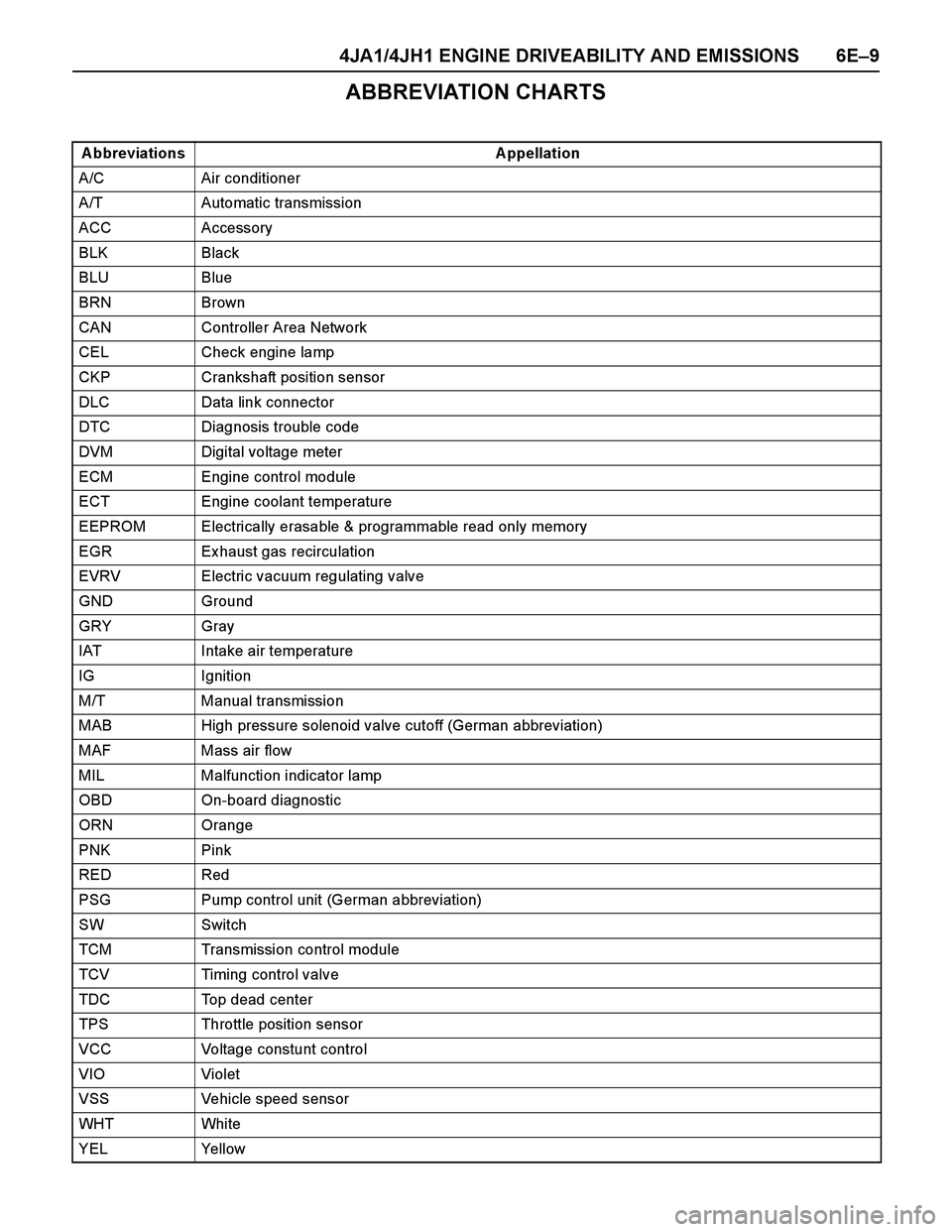
ABBREVIATION CHARTS
A bbreviations A ppellation
A/C Air conditioner
A/T Automatic transmission
ACC Accessory
BLK Black
BLU Blue
BRN Brown
CAN Controller Area Network
CEL Check engine lamp
CKP Crankshaft position sensor
DLC Data link connector
DTC Diagnosis trouble code
DVM Digital voltage meter
ECM Engine control module
ECT Engine coolant temperature
EEPROM Electrically erasable & programmable read only memory
EGR Ex haust gas recirculation
EVRV Electric vacuum regulating valve
GND Ground
GRY Gray
IAT Intake air temperature
IG Ignition
M/T Manual transmission
MAB High pressure solenoid valve cutoff (German abbreviation)
MAF Mass air flow
MIL Malfunction indicator lamp
OBD On-board diagnostic
ORN Orange
PNK Pink
RED Red
PSG Pump control unit (German abbreviation)
SW Switch
TCM Transmission control module
TCV Timing control valve
TDC Top dead center
TPS Throttle position sensor
VCC Voltage constunt control
VIO Violet
VSS Vehicle speed sensor
WHT Whi te
YEL Yellow
Page 1439 of 4264
4JA1/4JH1 ENGINE DRIVEABILITY AND EMISSIONS 6E–67
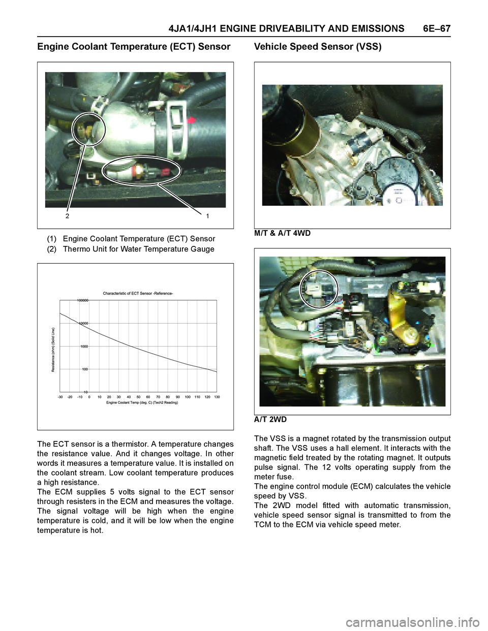
Engine Coolant Temperature (ECT) Sensor
The ECT sensor is a thermistor. A temperature changes
the resistance value. And it changes voltage. In other
words it measures a temperature value. It is installed on
the coolant stream. Low coolant temperature produces
a high resistance.
The ECM supplies 5 volts signal to the ECT sensor
through resisters in the ECM and measures the voltage.
The signal voltage will be high when the engine
temperature is cold, and it will be low when the engine
temperature is hot.
Vehicle Speed Sensor (VSS)
M/T & A /T 4WD
A/T 2WD
The VSS is a magnet rotated by the transmission output
shaft. The VSS uses a hall element. It interacts with the
magnetic field treated by the rotating magnet. It outputs
pulse signal. The 12 volts operating supply from the
meter fuse.
The engine control module (ECM) calculates the vehicle
speed by VSS.
The 2WD model fitted with automatic transmission,
vehicle speed sensor signal is transmitted to from the
TCM to the ECM via vehicle speed meter. (1) Engine Coolant Temperature (ECT) Sensor
(2) Thermo Unit for Water Temperature Gauge
12
Characteristic of ECT Sensor -Reference-
10 100 1000 10000 100000
-30 -20 -10 0 10 20 30 40 50 60 70 80 90 100 110 120 130
Engine Coolant Temp (deg. C) (Tech2 Reading)
Resistance (ohm) (Solid Line)
Page 1451 of 4264
4JA1/4JH1 ENGINE DRIVEABILITY AND EMISSIONS 6E–79
–Are there areas subjected to vibration or
movement (engine, transmission or
suspension)?
–Are there areas ex posed to moisture, road salt
or other corrosives (battery acid, oil or other
fluids)?
–Are there common mounting areas with other
systems/components?
–Have previous repairs been performed to wiring,
connectors, components or mounting areas
(causing pinched wires between panels and
drivetrain or suspension components without
causing and immediate problem)?
–Does the vehicle have aftermarket or dealer-
installed equipment (radios, telephone, etc.)
Step 2: Isolate the problem
At this point, you should have a good idea of what could
cause the present condition, as well as could not cause
the condition. Actions to take include the following:
Divide (and separate, where possible) the system or
circuit into smaller sections
Confine the problem to a smaller area of the vehicle
(start with main harness connections while removing
panels and trim as necessary in order to eliminate
large vehicle sections from further investigation)
For two or more circuits that do not share a common
power or ground, concentrate on areas where
harnesses are routed together or connectors are
shared (refer to the following hints)
Hints
Though the symptoms may vary, basic electrical failures
are generally caused by:
Loose connections:
–Open/high resistance in terminals, splices,
connectors or grounds
Incorrect connector/harness routing (usually in new
vehicles or after a repair has been made):
–Open/high resistance in terminals, splices,
connectors of grounds
Corrosion and wire damage:
–Open/high resistance in terminals, splices,
connectors of grounds
Component failure:
–Opens/short and high resistance in relays,
modules, switches or loads
Aftermarket equipment affecting normal operation of
other systems
You may isolate circuits by:
Unplugging connectors or removing a fuse to
separate one part of the circuit from another part
Operating shared circuits and eliminating those that
function normally from the suspect circuit
If only one component fails to operate, begin testingat the component
If a number of components do no operate, begin tests
at the area of commonality (such as power sources,
ground circuits, switches or major connectors)
What resources you should use
Whenever appropriate, you should use the following
resources to assist in the diagnostic process:
Service manual
Technical equipment (for data analysis)
Ex perience
Technical Assistance
Circuit testing tools
5d. Intermittent Diagnosis
By definition, an intermittent problem is one that does
not occur continuously and will occur when certain
conditions are met. All these conditions, however, may
not be obvious or currently known. Generally,
intermittents are caused by:
Faulty electrical connections and wiring
Malfunctioning components (such as sticking relays,
solenoids, etc.)
EMI/RFI (Electromagnetic/radio frequency
interference)
Aftermarket equipment
Intermittent diagnosis requires careful analysis of
suspected systems to help prevent replacing good
parts. This may involve using creativity and ingenuity to
interpret customer complaints and simulating all
ex ternal and internal system conditions to duplicate the
problem.
What you should do
Step 1: A cquire information
A thorough and comprehensive customer check sheet
is critical to intermittent problem diagnosis. You should
require this, since it will dictate the diagnostic starting
point. The vehicle service history file is another
source for accumulating information about the
complaint.
Step 2: A nalyze the intermittent problem
Analyze the customer check sheet and service history
file to determine conditions relevant to the suspect
system(s).
Using service manual information, you must identify,
trace and locate all electrical circuits related to the
malfunctioning system(s). If there is more than one
system failure, you should identify, trace and locate
areas of commonality shared by the suspect circuits.
Page 1457 of 4264
4JA1/4JH1 ENGINE DRIVEABILITY AND EMISSIONS 6E–85
DIAGNOSIS WITH Tech 2
If no codes are set:
Refer to F1: Data Display and identify the electrical
faults that are not indicated by trouble code.
Refer to “SYMPTOM DIAGNOSIS”.
If codes are set:
1. Record all trouble codes displayed by Tech 2 and
check id the codes are intermittent.
2. Clear the codes.
3. Drive the vehicle for a test to reproduce the faulty
status.
4. Check trouble codes again using the Tech 2.
5. If no codes is displayed by test driving, the fault is
intermittent. In this case, refer to “DIAGNOSIS
AIDS”.
6. If a code is present, refer to DTC Chart for
diagnosis.
7. Check trouble codes again using the Tech 2.
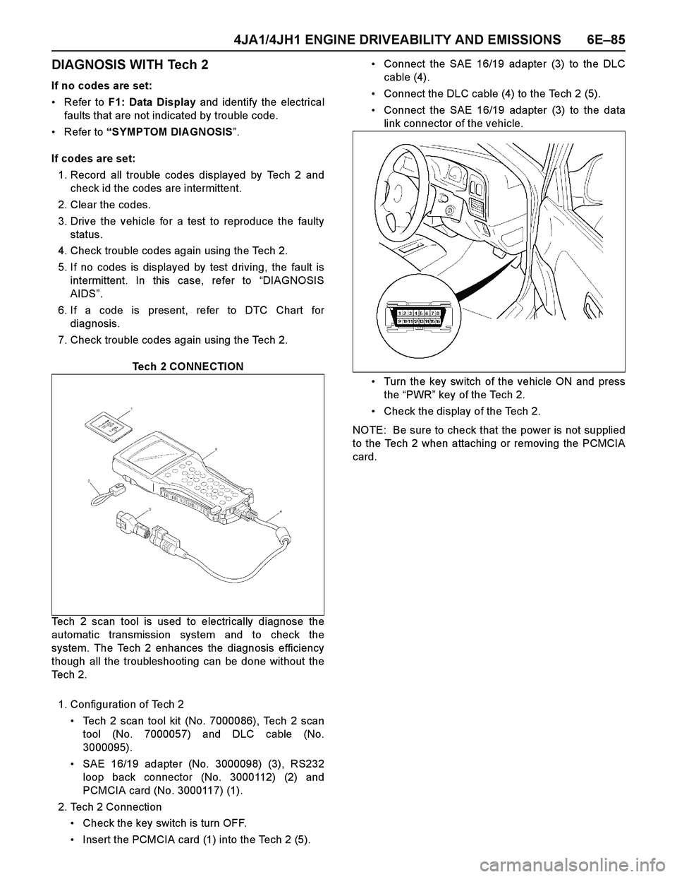
Tech 2 CONNECTION
Tech 2 scan tool is used to electrically diagnose the
automatic transmission system and to check the
system. The Tech 2 enhances the diagnosis efficiency
though all the troubleshooting can be done without the
Te c h 2 .
1. Configuration of Tech 2
Tech 2 scan tool kit (No. 7000086), Tech 2 scan
tool (No. 7000057) and DLC cable (No.
3000095).
SAE 16/19 adapter (No. 3000098) (3), RS232
loop back connector (No. 3000112) (2) and
PCMCIA card (No. 3000117) (1).
2. Tech 2 Connection
Check the key switch is turn OFF.
Insert the PCMCIA card (1) into the Tech 2 (5).Connect the SAE 16/19 adapter (3) to the DLC
cable (4).
Connect the DLC cable (4) to the Tech 2 (5).
Connect the SAE 16/19 adapter (3) to the data
link connector of the vehicle.
Turn the key switch of the vehicle ON and press
the “PWR” key of the Tech 2.
Check the display of the Tech 2.
NOTE: Be sure to check that the power is not supplied
to the Tech 2 when attaching or removing the PCMCIA
card.
Page 1472 of 4264
6E–100 4JA1/4JH1 ENGINE DRIVEABILITY AND EMISSIONS
2. Demand of Data
1. Connect Tech-2 to the vehicle. When activated by
turning on the power of Tech-2, push the “Enter”
switch.
2. Turn on the ignition switch (without starting the
engine)
3. In the main menu of Diagnostic Tester, push “F1:
Service Programming System (SPS)”.
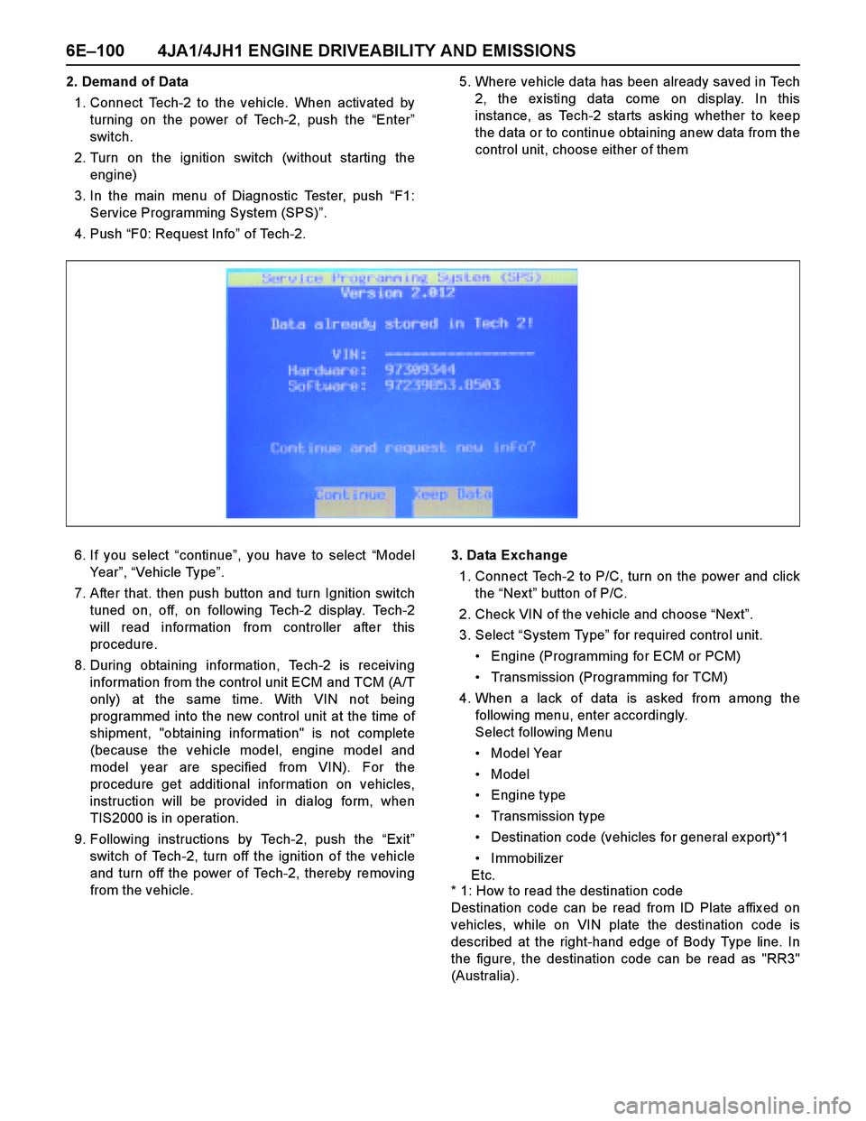
4. Push “F0: Request Info” of Tech-2.5. Where vehicle data has been already saved in Tech
2, the ex isting data come on display. In this
instance, as Tech-2 starts asking whether to keep
the data or to continue obtaining anew data from the
control unit, choose either of them
6. If you select “continue”, you have to select “Model
Year”, “Vehicle Type”.
7. After that. then push button and turn Ignition switch
tuned on, off, on following Tech-2 display. Tech-2
will read information from controller after this
procedure.
8. During obtaining information, Tech-2 is receiving
information from the control unit ECM and TCM (A/T
only) at the same time. With VIN not being
programmed into the new control unit at the time of
shipment, "obtaining information" is not complete
(because the vehicle model, engine model and
model year are specified from VIN). For the
procedure get additional information on vehicles,
instruction will be provided in dialog form, when
TIS2000 is in operation.
9. Following instructions by Tech-2, push the “Ex it”
switch of Tech-2, turn off the ignition of the vehicle
and turn off the power of Tech-2, thereby removing
from the vehicle.3. Data Exchange
1. Connect Tech-2 to P/C, turn on the power and click
the “Next” button of P/C.
2. Check VIN of the vehicle and choose “Next”.
3. Select “System Type” for required control unit.
Engine (Programming for ECM or PCM)
Transmission (Programming for TCM)
4. When a lack of data is asked from among the
following menu, enter accordingly.
Select following Menu
Model Year
Model
Engine type
Transmission type
Destination code (vehicles for general export)*1
Immobilizer
Etc.
* 1: How to read the destination code
Destination code can be read from ID Plate affix ed on
vehicles, while on VIN plate the destination code is
described at the right-hand edge of Body Type line. In
the figure, the destination code can be read as "RR3"
(Australia).
Page 1613 of 4264
4JA1/4JH1 ENGINE DRIVEABILITY AND EMISSIONS 6E–241
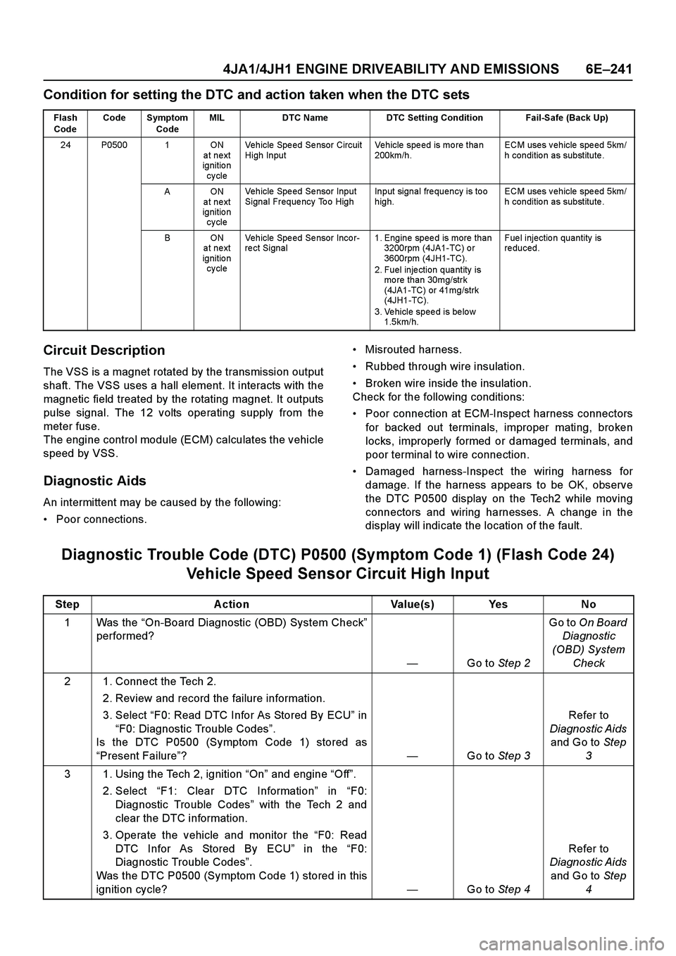
Condition for setting the DTC and action taken when the DTC sets
Circuit Description
The VSS is a magnet rotated by the transmission output
shaft. The VSS uses a hall element. It interacts with the
magnetic field treated by the rotating magnet. It outputs
pulse signal. The 12 volts operating supply from the
meter fuse.
The engine control module (ECM) calculates the vehicle
speed by VSS.
Diagnostic Aids
An intermittent may be caused by the following:
Poor connections.Misrouted harness.
Rubbed through wire insulation.
Broken wire inside the insulation.
Check for the following conditions:
Poor connection at ECM-Inspect harness connectors
for backed out terminals, improper mating, broken
locks, improperly formed or damaged terminals, and
poor terminal to wire connection.
Damaged harness-Inspect the wiring harness for
damage. If the harness appears to be OK, observe
the DTC P0500 display on the Tech2 while moving
connectors and wiring harnesses. A change in the
display will indicate the location of the fault.
Diagnostic Trouble Code (DTC) P0500 (Symptom Code 1) (Flash Code 24)
Vehicle Speed Sensor Circuit High Input
Flash
CodeCode Symptom
CodeMIL DTC Name DTC Setting Condition Fail-Safe (Back Up)
24 P0500 1 ON
at next
ignitio n
cy cleVehicle Spe ed Se nsor Circuit
High InputVehicle speed is more than
200km/h.ECM uses v ehicle spe ed 5km/
h condition as substitute.
AON
at next
ignitio n
cy cleVehicle Speed Sensor Input
Signal Frequency Too HighInput signal frequency is too
high.ECM uses v ehicle spe ed 5km/
h condition as substitute.
BON
at next
ignitio n
cy cleVehicle Spe ed Se nsor Inco r-
re ct Signal1. Engine speed is more than
3200rpm (4JA1-TC) o r
3600rpm (4JH1-TC).
2. Fuel injection quantity is
more than 30mg/strk
(4JA1-TC) or 41mg/strk
(4JH1-TC).
3. Vehicle speed is below
1.5km/h.Fuel injection quantity is
re duced.
Step Action Value(s) Yes No
1Was the “On-Board Diagnostic (OBD) System Check”
performed?
—Go to Step 2Go to On Board
Diagnostic
(OBD) System
Check
2 1. Connect the Tech 2.
2. Review and record the failure information.
3. Select “F0: Read DTC Infor As Stored By ECU” in
“F0: Diagnostic Trouble Codes”.
Is the DTC P0500 (Symptom Code 1) stored as
“Present Failure”?—Go to Step 3Refer to
Diagnostic Aids
and Go to Step
3
3 1. Using the Tech 2, ignition “On” and engine “Off”.
2. Select “F1: Clear DTC Information” in “F0:
Diagnostic Trouble Codes” with the Tech 2 and
clear the DTC information.
3. Operate the vehicle and monitor the “F0: Read
DTC Infor As Stored By ECU” in the “F0:
Diagnostic Trouble Codes”.
Was the DTC P0500 (Symptom Code 1) stored in this
ignition cycle?—Go to Step 4Refer to
Diagnostic Aids
and Go to Step
4
Page 1687 of 4264
4JA1/4JH1 ENGINE DRIVEABILITY AND EMISSIONS 6E–315
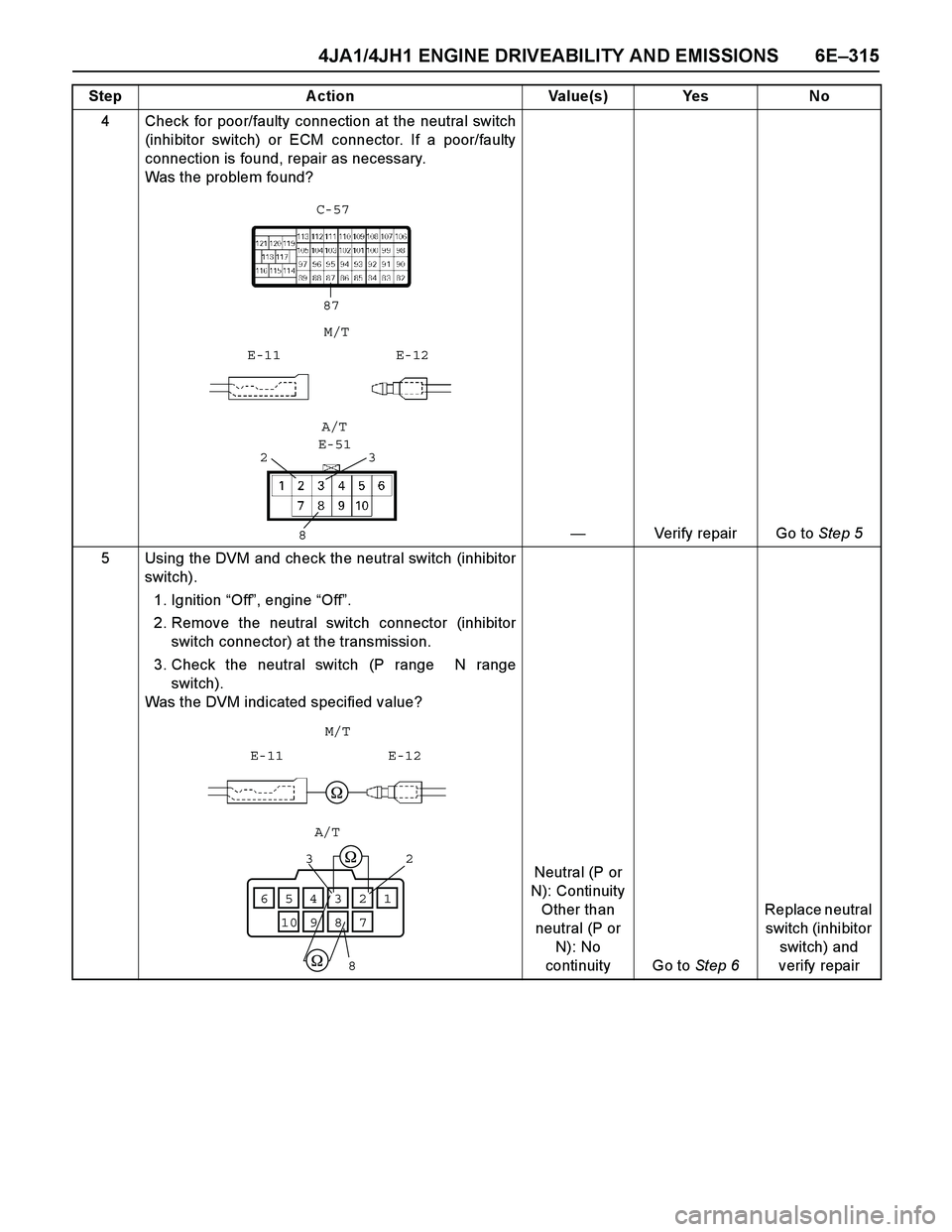
4 Check for poor/faulty connection at the neutral switch
(inhibitor switch) or ECM connector. If a poor/faulty
connection is found, repair as necessary.
Was the problem found?
—Verify repair Go to Step 5
5 Using the DVM and check the neutral switch (inhibitor
switch).
1. Ignition “Off”, engine “Off”.
2. Remove the neutral switch connector (inhibitor
switch connector) at the transmission.
3. Check the neutral switch (P range N range
switch).
Was the DVM indicated specified value?
Neutral (P or
N): Continuity
Other than
neutral (P or
N): No
continuity Go to Step 6Replace neutral
switch (inhibitor
switch) and
verify repair Step Action Value(s) Yes No
87 C-57
E-11M/TE-12
23
8E-51A/T
E-11 E-12M/T
123654
78109
8
32
A/T
Page 1838 of 4264
6A-14 ENGINE MECHANICAL (6VE1 3.5L)
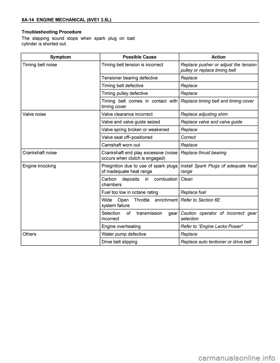
Troubleshooting Procedure
The slapping sound stops when spark plug on bad
cylinder is shorted out.
Symptom Possible Cause Action
Timing belt noise Timing belt tension is incorrect Replace pusher or adjust the tension
pulley or replace timing belt
Tensioner bearing defective Replace
Timing belt defective Replace
Timing pulley defective Replace
Timing belt comes in contact with
timing cover Replace timing belt and timing cover
Valve noise Valve clearance incorrect Replace adjusting shim
Valve and valve guide seized Replace valve and valve guide
Valve spring broken or weakened Replace
Valve seat off–positioned Correct
Camshaft worn out Replace
Crankshaft noise Crankshaft end play excessive (noise
occurs when clutch is engaged) Replace thrust bearing
Engine knocking Preignition due to use of spark plugs
of inadequate heat range Install Spark Plugs of adequate heat
range
Carbon deposits in combustion
chambers Clean
Fuel too low in octane rating Replace fuel
Wide Open Throttle enrichment
system failure Refer to Section 6E
Selection of transmission gear
incorrect Caution operator of incorrect gear
selection
Engine overheating Refer to “Engine Lacks Power"
Others Water pump defective Replace
Drive belt slipping Replace auto tentioner or drive belt