Page 2249 of 4264
3.5L ENGINE DRIVEABILITY AND EMISSIONS 6E-253
Step Action Value (s) Yes No
7
Using the DVM and check the ignition coil signal
circuit for the affected cylinder.
Breaker box is available:
1. Ignition "Off", engine "Off".
2. Install the breaker box as type A (ECM
disconnected).
Refer to 6E-95 page.
3. Disconnect the ignition coil connector for the
affected cylinder.
4. Check the circuit for open or short to ground circuit.
Was the problem found?
A32
Breaker Box No.1 Cylinder
�
E-53
�
�
B7
Breaker Box No.2 Cylinder
�
E-54
�
�
A31
Breaker Box No.3 Cylinder
�
E-55
�
�
B8
Breaker Box No.4 Cylinder
�
E-56
�
�
A30
Breaker Box No.5 Cylinder
�
E-57
�
�
Page 2250 of 4264
6E-254 3.5L ENGINE DRIVEABILITY AND EMISSIONS
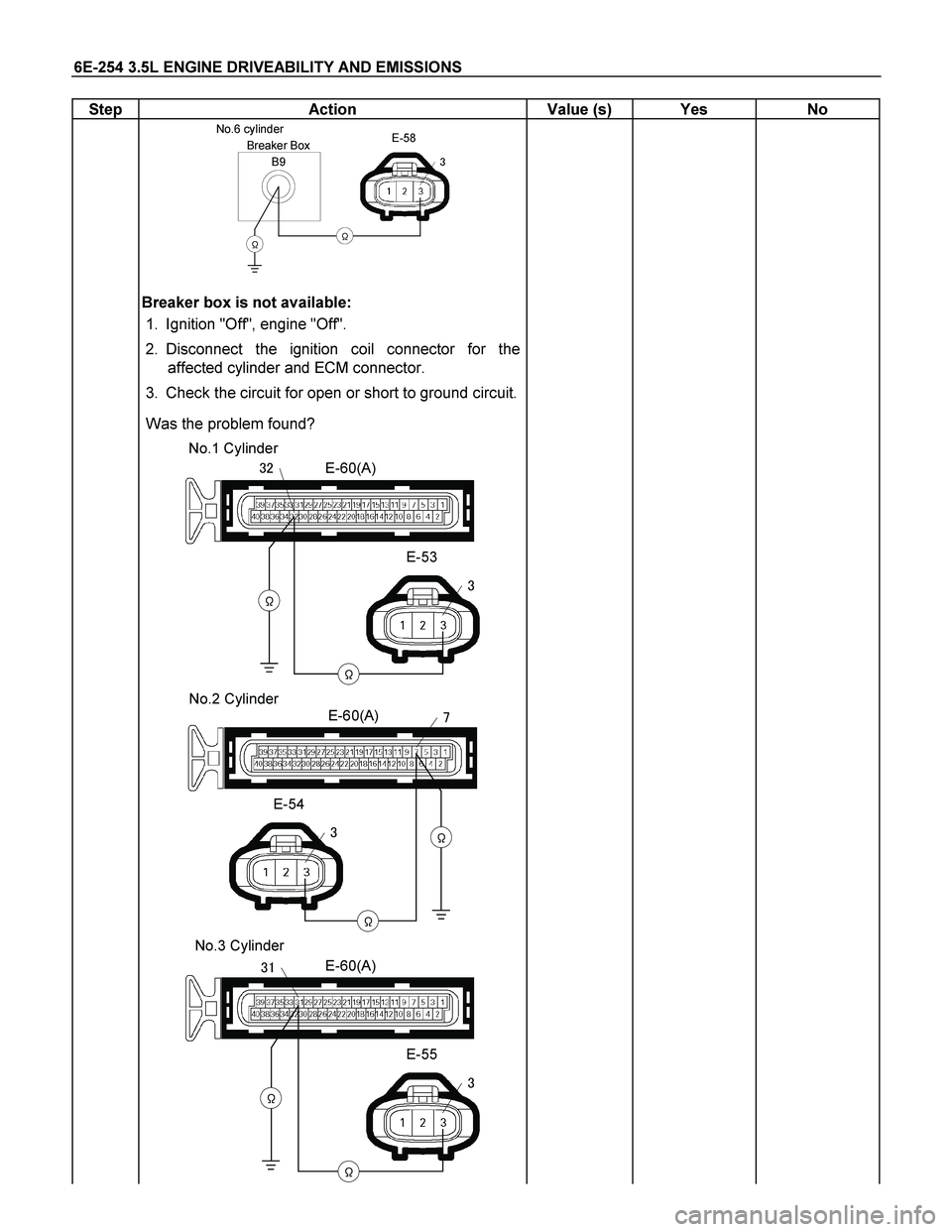
Step Action Value (s) Yes No
B9
Breaker Box No.6 cylinder
�
E-58
�
�
Breaker box is not available:
1. Ignition "Off", engine "Off".
2. Disconnect the ignition coil connector for the
affected cylinder and ECM connector.
3. Check the circuit for open or short to ground circuit.
Was the problem found?
E-60(A)
E-53
�
�
�
�� No.1 Cylinder
E-60(A)
E-54
�
�
�
�
No.2 Cylinder
E-60(A)
E-55
�
�
�
�� No.3 Cylinder
Page 2252 of 4264
6E-256 3.5L ENGINE DRIVEABILITY AND EMISSIONS
Step Action Value (s) Yes No
8
Using the DVM and check the ignition coil power
supply circuit.
1. Ignition "On", engine "Off".
2. Disconnect the ignition coil connector for the
affected cylinder.
3. Check the circuit for open circuit.
Was the DVM indicated specified value?
E-53/E-54/E-55/
E-56/E-57/E-58
V
�
10-14.5V
Go to Step 10
Go to Step 9
9
Repair the open or short to ground circuit between the
"IGN. COIL" (15A) and ignition coil for the affected
cylinder.
Is the action complete?
- Verify repair -
10
Using the DVM and check the ignition coil ground
circuit for the affected cylinder.
1. Ignition "On", engine "Off".
2. Disconnect the ignition coil connector for the
affected cylinder.
3. Check the circuit for short to power supply circuit.
Was the DVM indicated specified value?
E-53/E-54/E-55/
E-56/E-57/E-58
V
�
Less than 1V
Go to Step 11
Repair faulty
harness and
verify repair
Page 2253 of 4264
 Yes No
11
Using the DVM and check the ignition coil ground
circuit.
1. Ignition \"Off\", engine \"Off\".
2. Disconnect the")
3.5L ENGINE DRIVEABILITY AND EMISSIONS 6E-257
Step Action Value (s) Yes No
11
Using the DVM and check the ignition coil ground
circuit.
1. Ignition "Off", engine "Off".
2. Disconnect the ignition coil connector for the
affected cylinder and ECM connector.
3. Check the circuit for open circuit.
Was the problem found?
E-53/E-54/E-55/
E-56/E-57/E-58
�
�
- Repair faulty
harness and
verify repair Go to Step 12
12
Replace the ignition coil for the affected cylinder.
Was the problem solved?
- Verify repair Go to Step 13
13
Is the ECM programmed with the latest software
release?
If not, download the latest software to the ECM using
the "SPS (Service Programming System)".
Was the problem solved?
- Verify repair Go to Step 14
14
Replace the ECM.
Is the action complete?
IMPORTANT: The replacement ECM must be
programmed. Refer to section of the Service
Programming System (SPS) in this manual. Following
ECM programming, the immobilizer system (if
equipped) must be linked to the ECM. Refer to section
11 “Immobilizer System-ECM replacement” for the
ECM/Immobilizer linking procedure.
- Verify repair -
Page 2256 of 4264
 Yes No
4
Check for poor/faulty connection at the EGR valve or
ECM connector. If a poor/faulty connection is found,
repair")
6E-260 3.5L ENGINE DRIVEABILITY AND EMISSIONS
Step Action Value (s) Yes No
4
Check for poor/faulty connection at the EGR valve or
ECM connector. If a poor/faulty connection is found,
repair as necessary.
Was the problem found?
E-60(A)
E-76
�
��
- Verify repair Go to Step 5
5
Using the DVM and check the EGR valve.
1. Ignition "Off", engine "Off".
2. Disconnect EGR valve connector.
3. Measure the resistance of EGR valve solenoid coil.
Does the tester indicate standard resistance?
EGR Valve
�
��
Apporoximately
8.3� at 20�C
Go to Step 6
Go to Step 11
6
Inspect the EGR valve.
1. Remove the EGR valve from the engine.
2. Inspect the EGR valve whether there is any carbon
deposit on shaft.
If excessive carbon deposit is found, clean up the
EGR valve and inspect damage of the pintle and seat.
Was the problem found?
-
Verify repair or
Go to Step 11
Go to Step 7
7
Using the DVM and check the EGR valve solenoid
power supply circuit.
1. Ignition "On", engine "Off".
2. Disconnect the EGR valve connector.
3. Check the circuit for open circuit.
Was the DVM indicated specified value?
E-76
V
�
10-14.5 V
Go to Step 9
Go to Step 8
Page 2272 of 4264
6E-276 3.5L ENGINE DRIVEABILITY AND EMISSIONS
Step Action Value (s) Yes No
4
Check for poor/faulty connection at the purge solenoid
valve or ECM connector. If a poor/faulty connection is
found, repair as necessary.
Was the problem found?
E-61(B)
E-66
��
��
- Verify repair Go to Step 5
5
Using the DVM and check the purge solenoid valve.
1. Ignition "Off", engine "Off".
2. Disconnect purge solenoid valve connector.
3. Measure the resistance of purge solenoid valve
coil.
Does the tester indicate standard resistance?
25 - 30� at
20�C
Go to Step 6
Go to Step 9
6
Using the DVM and check the purge solenoid valve
power supply circuit.
1. Ignition "On", engine "Off".
2. Disconnect the purge solenoid valve connector.
3. Check the circuit for open circuit.
Was the DVM indicated specified value?
E-66
V
�
10-14.5V
Go to Step 8
Go to Step 7
7
Repair the open or short to ground circuit between the
"Engine" fuse (15A) and purge solenoid valve.
Is the action complete?
- Verify repair -
Page 2293 of 4264

P1508 B")
3.5L ENGINE DRIVEABILITY AND EMISSIONS 6E-297
Condition For Setting The DTC and Action Taken When The DTC Sets
Flash
Code Code Type DTC Name DTC Setting Condition Fail-Safe (Back Up)
P1508 B Idle Air Control System
Low/Closed 1. No DTC relating to MAF sensor, IAT sensor, ECT sensor,
TPS, CMP sensor, CKP sensor, VSS and system voltage.
2. Engine speed is between 675rpm and 6000rpm.
3. Engine coolant temperature is more than 75�C.
4. Intake air temperature is between -10�C and 80�C.
5. Vehicle is stopping.
6. Small amount of intake air through the idle air control
valve. (Idle air control valve is sticking at close position.)
Above conditions are met for 2 seconds. 22
P1509 B Idle Air Control System
High/Open 1. No DTC relating to MAF sensor, IAT sensor, ECT sensor,
TPS, CMP sensor, CKP sensor, VSS and system voltage.
2. Engine speed is between 675rpm and 6000rpm.
3. Engine coolant temperature more than 75�C.
4. Intake air temperature is between -10�C and 80�C.
5. Vehicle is stopping.
6. Large amount of intake air through the idle air control
valve. (Idle air control valve is sticking at open position.)
Above conditions are met for 2 seconds. Fuel cut is operated at high idle
speed.
CIRCUIT DESCRIPTION
The engine control module (ECM) controls engine idle
speed by adjusting the position of the idle air control
(IAC) motor pintle. The IAC is a bi-directional steppe
r
motor driven by two coils. The ECM applies current to
the IAC coils in steps (counts) to extend the IAC pintle
into a passage in the throttle body to decrease air flow.
The ECM reverses the current to retract the pintle,
increasing air flow. This method allows highly accurate
control of idle speed and quick response to changes in
engine load. If the ECM detects a condition where too
low of an idle speed is present and the ECM is unable
to adjust idle speed by increasing the IAC counts, DTC
P1508 or P1509 will set, indicating a problem with the
idle control system.
DIAGNOSTIC AIDS
Check for the following conditions:
Poor connection at ECM or IAC motor –Inspec
t
harness connectors for backed-out terminals,
improper mating, broken locks, improperly formed o
r
damaged terminals, and poor terminal-to-wire
connection.
Damaged harness – Inspect the wiring for damage.
Restricted air intake system – Check for a possible
collapsed air intake duct, restricted air filter element,
or foreign objects blocking the air intake system.
Page 2295 of 4264
3.5L ENGINE DRIVEABILITY AND EMISSIONS 6E-299
Step Action Value (s) Yes No
6
Remove the IAC Valve and visually check.
Was the problem found?
- Go to Step 12 Go to Step 7
7
Using the DVM and check the IAC Valve coil at IAC
Valve.
1. Ignition "Off", engine "Off".
2. Disconnect the IAC Valve connector.
3. Check the coil resistance.
Does the tester indicate standard resistance as shown
in the following table?
IAC Valve
��
��
���
�
�
�
Measurement Terminal Resistance (�)
1 - 2 Approximately 50�
2 - 3 Approximately 50�
1 – 3 Approximately 100�
4 - 5 Approximately 50�
5 - 6 Approximately 50�
4 - 6 Approximately 100�
-
Go to Step 8
Go to Step 12
8
Using the DVM and check the IAC Valve power supply
circuit.
1. Ignition "Off", engine "Off".
2. Disconnect the IAC Valve connector and ECM
main relay
3. Check the circuit for open circuit.
Was the problem found?
X-13E-70
�
�
�
�
�
-
Repair faulty
harness and
verify repair
Go to Step 9
 Yes No
7
Using the DVM and check the ignition coil signal
circuit for the affected cylinder.
Breaker box is available:")
 Yes No
8
Using the DVM and check the ignition coil power
supply circuit.
1. Ignition \"On\", engine \"Off\".
2. Disconnect")
 Yes No
4
Check for poor/faulty connection at the purge solenoid
valve or ECM connector. If a poor/faulty connection is
fou")
 Yes No
6
Remove the IAC Valve and visually check.
Was the problem found?
- Go to Step 12 Go to Step 7
7
Using the DVM")