Page 2103 of 4264
3.5L ENGINE DRIVEABILITY AND EMISSIONS 6E -107
Injector Coil Test Procedure (Steps 1-6) and Injector Balance Test Procedure
(Steps 7-11)
CYLINDER 1 2 3 4 5 6
1st Reading (1) 296 kPa
(43 psi) 296 kPa
(43 psi) 296 kPa
(43 psi) 296 kPa
(43 psi) 296 kPa
(43 psi) 296 kPa
(43 psi)
2nd Reading (2) 131 kPa
(19 psi) 117 kPa
(17 psi) 124 kPa
(18 psi) 145 kPa
(21 psi) 131 kPa
(19 psi) 130 kPa
(19 psi)
Amount of Drop
(1st Reading–2nd Reading) 165 kPa
(24 psi) 179 kPa
(26 psi) 172 kPa
(25 psi) 151 kPa
(22 psi) 165 kPa
(24 psi) 166 kPa
(24 psi)
Av.drop = 166 kPa/24 psi
��10 kPa/1.5 psi
= 156- 176 kPa or
22.5- 25.5 psi OK Faulty, Rich
(Too Much
Fuel Drop) OK Faulty, Lean
( Too Little
Fuel Drop) OK OK
NOTE: These figures are examples only.
Page 2104 of 4264
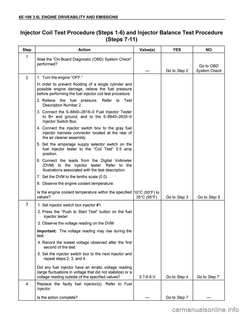
6E-108 3.5L ENGINE DRIVEABILITY AND EMISSIONS
Injector Coil Test Procedure (Steps 1-6) and Injector Balance Test Procedure
(Steps 7-11)
Step Action Value(s) YES NO
1
Was the “On-Board Diagnostic (OBD) System Check"
performed?
— Go to Step 2 Go to OBD
System Check
2 1. Turn the engine “OFF."
In order to prevent flooding of a single cylinder and
possible engine damage, relieve the fuel pressure
before performing the fuel injector coil test procedure.
2. Relieve the fuel pressure. Refer to Test
Description Number 2.
3. Connect the 5–8840–2618–0 Fuel Injector Tester
to B+ and ground, and to the 5–8840–2635–0
Injector Switch Box.
4. Connect the injector switch box to the gray fuel
injector harness connector located at the rear of
the air cleaner assembly.
5. Set the amperage supply selector switch on the
fuel injector tester to the “Coil Test" 0.5 amp
position.
6. Connect the leads from the Digital Voltmeter
(DVM) to the injector tester. Refer to the
illustrations associated with the test description.
7. Set the DVM to the tenths scale (0.0).
8. Observe the engine coolant temperature.
Is the engine coolant temperature within the specified
values? 10�C (50�F) to
35�C (95�F) Go to Step 3 Go to Step 5
3
1. Set injector switch box injector #1.
2. Press the “Push to Start Test" button on the fuel
injector tester.
3. Observe the voltage reading on the DVM.
Important: The voltage reading may rise during the
test.
4. Record the lowest voltage observed after the first
second of the test.
5. Set the injector switch box to the next injector and
repeat steps 2, 3, and 4.
Did any fuel injector have an erratic voltage reading
(large fluctuations in voltage that did not stabilize) or a
voltage reading outside of the specified values? 5.7-6.6 V Go to Step 4 Go to Step 7
4 Replace the faulty fuel injector(s). Refer to Fuel
Injector.
Is the action complete? — Go to Step 7 —
Page 2109 of 4264
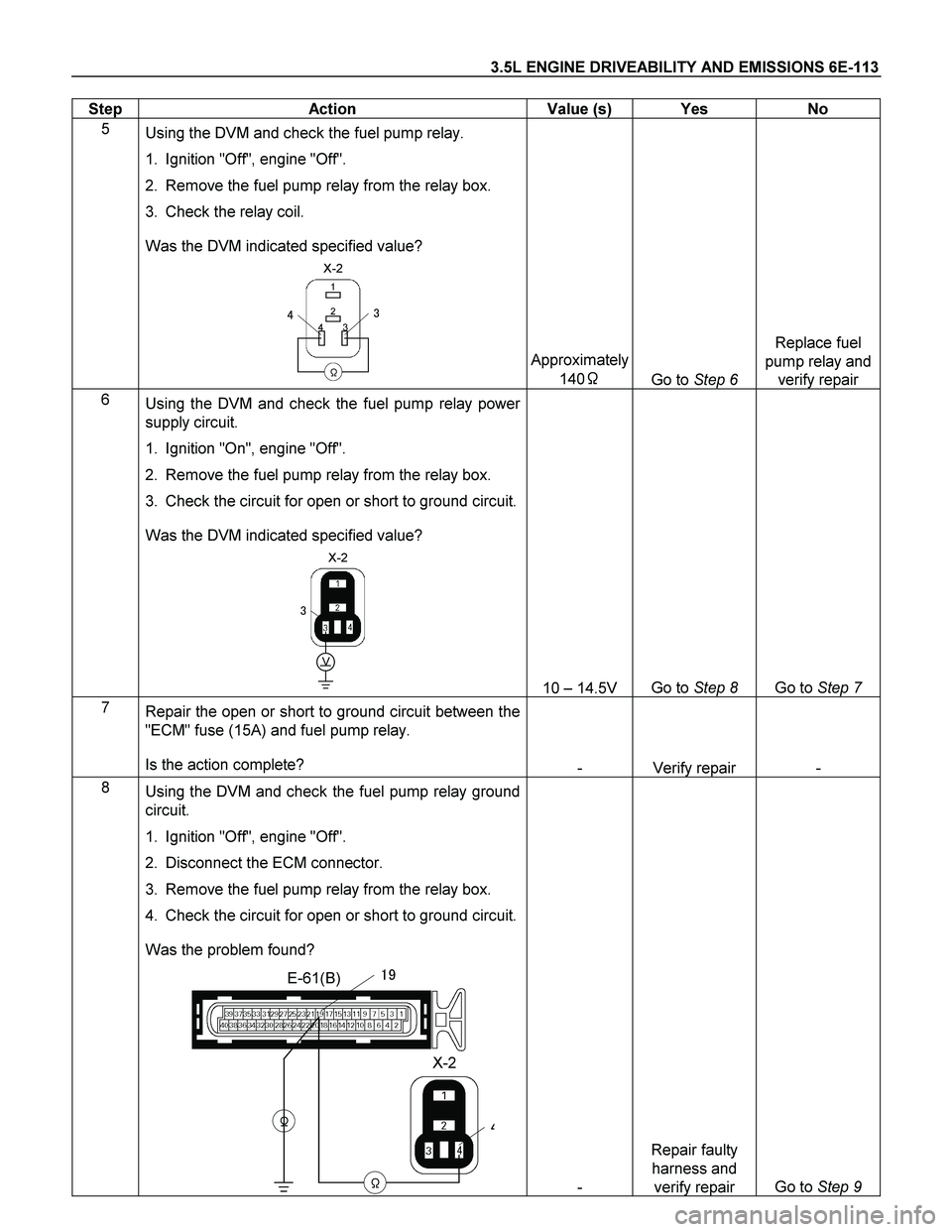
3.5L ENGINE DRIVEABILITY AND EMISSIONS 6E-113
Step Action Value (s) Yes No
5
Using the DVM and check the fuel pump relay.
1. Ignition "Off", engine "Off".
2. Remove the fuel pump relay from the relay box.
3. Check the relay coil.
Was the DVM indicated specified value?
X-2
�
1
3 2
4
�
��
Approximately
140�
Go to Step 6 Replace fuel
pump relay and
verify repair
6
Using the DVM and check the fuel pump relay power
supply circuit.
1. Ignition "On", engine "Off".
2. Remove the fuel pump relay from the relay box.
3. Check the circuit for open or short to ground circuit.
Was the DVM indicated specified value?
X-2
�
V
�
10 – 14.5V Go to Step 8 Go to Step 7
7
Repair the open or short to ground circuit between the
"ECM" fuse (15A) and fuel pump relay.
Is the action complete?
- Verify repair -
8
Using the DVM and check the fuel pump relay ground
circuit.
1. Ignition "Off", engine "Off".
2. Disconnect the ECM connector.
3. Remove the fuel pump relay from the relay box.
4. Check the circuit for open or short to ground circuit.
Was the problem found?
E-61(B)
X-2
�
�
�
�
��
- Repair faulty
harness and
verify repair Go to Step 9
Page 2118 of 4264
6E-122 3.5L ENGINE DRIVEABILITY AND EMISSIONS
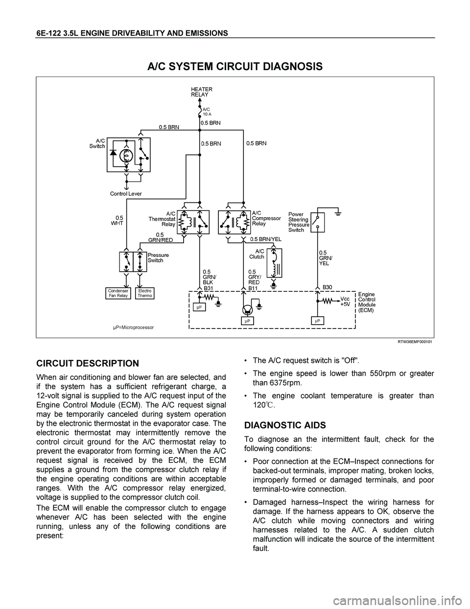
A/C SYSTEM CIRCUIT DIAGNOSIS
RTW36EMF000101
CIRCUIT DESCRIPTION
When air conditioning and blower fan are selected, and
if the system has a sufficient refrigerant charge, a
12-volt signal is supplied to the A/C request input of the
Engine Control Module (ECM). The A/C request signal
may be temporarily canceled during system operation
by the electronic thermostat in the evaporator case. The
electronic thermostat may intermittently remove the
control circuit ground for the A/C thermostat relay to
prevent the evaporator from forming ice. When the A/C
request signal is received by the ECM, the ECM
supplies a ground from the compressor clutch relay i
f
the engine operating conditions are within acceptable
ranges. With the A/C compressor relay energized,
voltage is supplied to the compressor clutch coil.
The ECM will enable the compressor clutch to engage
whenever A/C has been selected with the engine
running, unless any of the following conditions are
present:
The A/C request switch is "Off".
The engine speed is lower than 550rpm or greate
r
than 6375rpm.
The engine coolant temperature is greater than
120�.
DIAGNOSTIC AIDS
To diagnose an the intermittent fault, check for the
following conditions:
Poor connection at the ECM–Inspect connections fo
r
backed-out terminals, improper mating, broken locks,
improperly formed or damaged terminals, and poo
r
terminal-to-wire connection.
Damaged harness–Inspect the wiring harness fo
r
damage. If the harness appears to OK, observe the
A/C clutch while moving connectors and wiring
harnesses related to the A/C. A sudden clutch
malfunction will indicate the source of the intermitten
t
fault.
Page 2120 of 4264
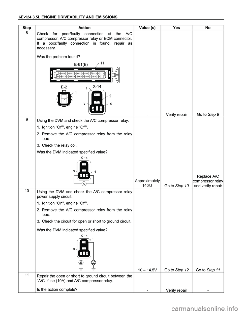
6E-124 3.5L ENGINE DRIVEABILITY AND EMISSIONS
Step Action Value (s) Yes No
8
Check for poor/faulty connection at the A/C
compressor, A/C compressor relay or ECM connector.
If a poor/faulty connection is found, repair as
necessary.
Was the problem found?
E-2
�
X-14
�
�
�
�
�
E-61(B)��
- Verify repair Go to Step 9
9
� Using the DVM and check the A/C compressor relay.
1. Ignition "Off", engine "Off".
2. Remove the A/C compressor relay from the relay
box.
3. Check the relay coil.
Was the DVM indicated specified value?
X-14
���
�
Approximately
140�
Go to Step 10 Replace A/C
compressor relay
and verify repair
10
Using the DVM and check the A/C compressor relay
power supply circuit.
1. Ignition "On", engine "Off".
2. Remove the A/C compressor relay from the relay
box.
3. Check the circuit for open or short to ground circuit.
Was the DVM indicated specified value?
X-14
�
�
�
VV
10 – 14.5V Go to Step 12 Go to Step 11
11
Repair the open or short to ground circuit between the
"A/C" fuse (10A) and A/C compressor relay.
Is the action complete?
- Verify repair -
Page 2122 of 4264
6E-126 3.5L ENGINE DRIVEABILITY AND EMISSIONS
Step Action Value (s) Yes No
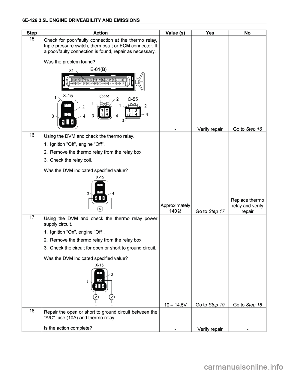
15
Check for poor/faulty connection at the thermo relay,
triple pressure switch, thermostat or ECM connector. If
a poor/faulty connection is found, repair as necessary.
Was the problem found?
E-61(B)
X-15
�
�
�
�
�
C-24C-55��
��
�
�
�
�
��
- Verify repair Go to Step 16
16
� Using the DVM and check the thermo relay.
1. Ignition "Off", engine "Off".
2. Remove the thermo relay from the relay box.
3. Check the relay coil.
Was the DVM indicated specified value?
X-15
���
�
Approximately
140�
Go to Step 17 Replace thermo
relay and verify
repair
17
� Using the DVM and check the thermo relay power
supply circuit.
1. Ignition "On", engine "Off".
2. Remove the thermo relay from the relay box.
3. Check the circuit for open or short to ground circuit.
Was the DVM indicated specified value?
X-15
�
�
�
VV
10 – 14.5V Go to Step 19 Go to Step 18
18
Repair the open or short to ground circuit between the
"A/C" fuse (10A) and thermo relay.
Is the action complete?
- Verify repair -
Page 2133 of 4264
3.5L ENGINE DRIVEABILITY AND EMISSIONS 6E-137
Flash
Code Code Type DTC Name DTC Setting Condition Fail-Safe (Back Up) Recovery Condition Related Failure Parts Related
ECM Pin
No. Related
Multiple
DTC
P0351 A Ignition 1 Control Circuit
A32 - P0352 A Ignition 2 Control Circuit
B7 - P0353 A Ignition 3 Control Circuit
A31 - P0354 A Ignition 4 Control Circuit
B8 - P0355 A Ignition 5 Control Circuit
A30 -
42
P0356 A Ignition 6 Control Circuit 1. No DTC relating to CMP sensor and CKP
sensor.
2. Engine speed is between 250rpm and 850
rpm.
3. 10 ignition signals are not detected
consecutively. Fuel cut is operated more than
2000rpm. 10 ignition signals are detected
consecutively. 1. Ignition coil harness open circuit, short to
ground or short to voltage.
2. Ignition coil malfunction.
3. ECM malfunction.
B9 -
Page 2142 of 4264
6E-146 3.5L ENGINE DRIVEABILITY AND EMISSIONS
CIRCUIT DESCRIPTION
The mass air flow (MAF) sensor measures the amount
of air which passes through it into the engine during a
given time. The Engine Control Module (ECM) uses the
mass air flow information to monitor engine operating
conditions for fuel delivery calculations. A large quantity
of air entering the engine indicates an acceleration o
r
high load situation, while a small quantity or air indicates
deceleration or idle.
The MAF sensor produces a frequency signal which
can be monitored using a Tech 2. The frequency will
vary within a range of around 4 to 7 g/s at idle to around
25 to 40 g/s at maximum engine load. DTC P0101 will
be set if the signal from the MAF sensor does not match
a predicted value based on throttle position and engine
RPM.
DIAGNOSTIC AIDS
An intermittent may be caused by the following:
Poor connections.
Mis-routed harness.
Rubbed through wire insulation.
Broken wire inside the insulation.
Refer to Intermittents under service category
Symptoms.
Any un-metered air may cause this DTC to set. Check
for the following:
The duct work at the MAF sensor for leaks.
An engine vacuum leak.
The PCV system for vacuum leaks.
An incorrect PCV valve.
The engine oil dip stick not fully seated.
The engine oil fill cap loose or missing.
Diagnostic Trouble Code (DTC) P0101 (Flash Code 61)
Mass Air Flow Sensor Circuit Range/Performance
Step Action Value (s) Yes No
1
Was the "On-Board Diagnostic (OBD) System Check"
performed?
- Go to Step 2 Go to On Board
Diagnostic (OBD)
System Check
2
1. Connect the Tech 2.
2. Review and record the failure information.
3. Select "F0: Read DTC Infor By Priority" in "F0:
Diagnostic Trouble Code".
Is the DTC P0101 stored as "Present Failure"?
- Go to Step 3 Refer to
Diagnostic Aids
and Go to Step 3
3
1. Using the Tech2, ignition "On" and engine "Off".
2. Select "Clear DTC Information" with the Tech2 and
clear the DTC information.
3. Operate the vehicle and monitor the "F5: Failed
This Ignition" in "F2: DTC Information"
Was the DTC P0101 stored in this ignition cycle?
- Go to Step 4 Refer to
Diagnostic Aids
and Go to Step 4