Page 2432 of 4264

6A-12 ENGINE MECHANICAL (C24SE)
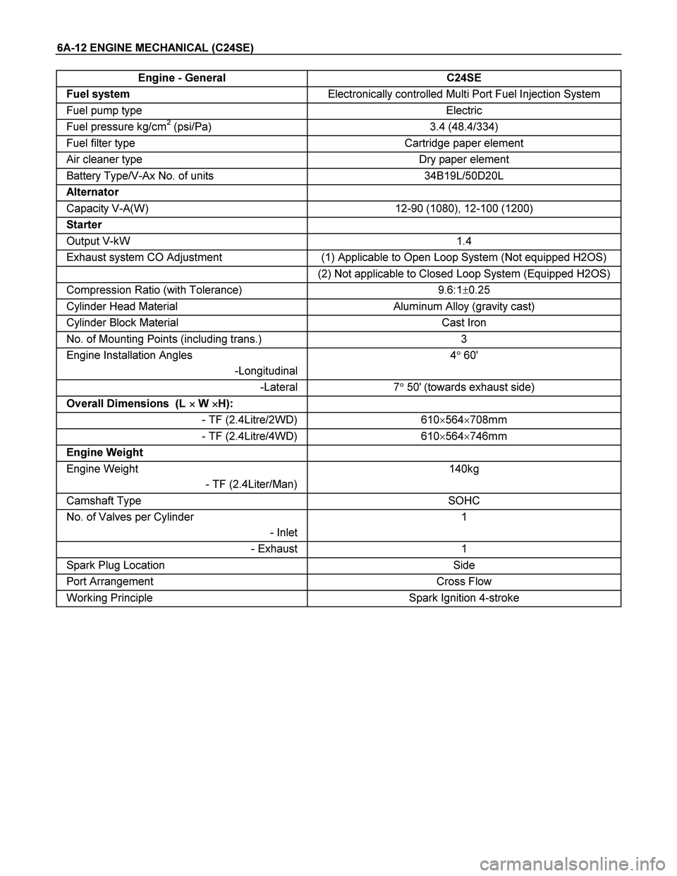
Engine - General C24SE
Fuel system Electronically controlled Multi Port Fuel Injection System
Fuel pump type Electric
Fuel pressure kg/cm2 (psi/Pa) 3.4 (48.4/334)
Fuel filter type Cartridge paper element
Air cleaner type Dry paper element
Battery Type/V-Ax No. of units 34B19L/50D20L
Alternator
Capacity V-A(W) 12-90 (1080), 12-100 (1200)
Starter
Output V-kW 1.4
Exhaust system CO Adjustment (1) Applicable to Open Loop System (Not equipped H2OS)
(2) Not applicable to Closed Loop System (Equipped H2OS)
Compression Ratio (with Tolerance) 9.6:1�0.25
Cylinder Head Material Aluminum Alloy (gravity cast)
Cylinder Block Material Cast Iron
No. of Mounting Points (including trans.) 3
Engine Installation Angles
-Longitudinal4� 60'
-Lateral 7� 50' (towards exhaust side)
Overall Dimensions (L �
�� � W �
�� �H):
- TF (2.4Litre/2WD) 610�564�708mm
- TF (2.4Litre/4WD) 610�564�746mm
Engine Weight
Engine Weight
- TF (2.4Liter/Man)140kg
Camshaft Type SOHC
No. of Valves per Cylinder
- Inlet1
- Exhaust 1
Spark Plug Location Side
Port Arrangement Cross Flow
Working Principle Spark Ignition 4-stroke
Page 2455 of 4264

ENGINE MECHANICAL (C24SE) 6A-35
Camshaft Housing, Removal and
Installation
Cylinder Head
Important!
Remove cylinder head only from cold engine (room
temperature).
Removal
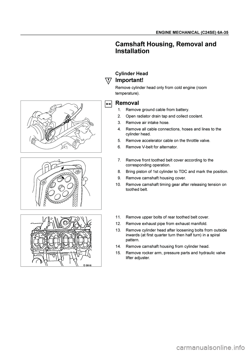
1. Remove ground cable from battery.
2. Open radiator drain tap and collect coolant.
3. Remove air intake hose.
4. Remove all cable connections, hoses and lines to the
cylinder head.
5. Remove accelerator cable on the throttle valve.
6. Remove V-belt for alternator.
7. Remove front toothed belt cover according to the
corresponding operation.
8. Bring piston of 1st cylinder to TDC and mark the position.
9. Remove camshaft housing cover.
10. Remove camshaft timing gear after releasing tension on
toothed belt.
11. Remove upper bolts of rear toothed belt cover.
12. Remove exhaust pipe from exhaust manifold.
13. Remove cylinder head after loosening bolts from outside
inwards (at first quarter turn then half turn) in a spiral
pattern.
14. Remove camshaft housing from cylinder head.
15. Remove rocker arm, pressure parts and hydraulic valve
lifter adjuster.
Page 2456 of 4264

6A-36 ENGINE MECHANICAL (C24SE)
Clean
All sealing surfaces, drill holes in cylinder head bolts.
Check cylinder block and cylinder head for plane surface
according to the corresponding operations.
Installation
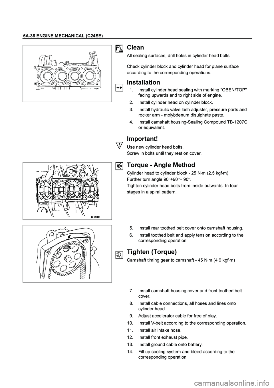
1. Install cylinder head sealing with marking "OBEN/TOP"
facing upwards and to right side of engine.
2. Install cylinder head on cylinder block.
3. Install hydraulic valve lash adjuster, pressure parts and
rocker arm - molybdenum disulphate paste.
4. Install camshaft housing-Sealing Compound TB-1207C
or equivalent.
Important!
Use new cylinder head bolts.
Screw in bolts until they rest on cover.
Torque - Angle Method
Cylinder head to cylinder block - 25 N�
m (2.5 kgf�
m)
Further turn angle 90�
+90�
+ 90�
.
Tighten cylinder head bolts from inside outwards. In four
stages in a spiral pattern.
5. Install rear toothed belt cover onto camshaft housing.
6. Install toothed belt and apply tension according to the
corresponding operation.
Tighten (Torque)
Camshaft timing gear to camshaft - 45 N�
m (4.6 kgf�
m)
7. Install camshaft housing cover and front toothed belt
cover.
8. Install cable connections, all hoses and lines onto
cylinder head.
9. Adjust accelerator cable for free of play.
10. Install V-belt according to the corresponding operation.
11. Install air intake hose.
12. Install front exhaust pipe.
13. Install ground cable onto battery.
14. Fill up cooling system and bleed according to the
corresponding operation.
Page 2485 of 4264
ENGINE MECHANICAL (C24SE) 6A-65
ENGINE EXTERNAL PARTS
Radiator
Removal
1. Disconnect battery ground cable.
2. Loosen a drain plug to drain EC.
3. Disconnect radiator inlet hose and outlet hose from the engine.
RTW46BSH000101
4. Remove fan guide(1), clips(2) on both sides and the
bottom lock, then remove lower fan guide(3) with fan
shroud(4).
5. Disconnect the reserve tank hose(6) from radiator.
RTW36BMH000101
6. Remove bracket(5).
7. Lift up and remove the radiator assembly with hose,
taking care not to damage the radiator core with a fan
blade.
Page 2487 of 4264

ENGINE MECHANICAL (C24SE) 6A-67
Coating sealing surfaces with Silicone Grease
Installation
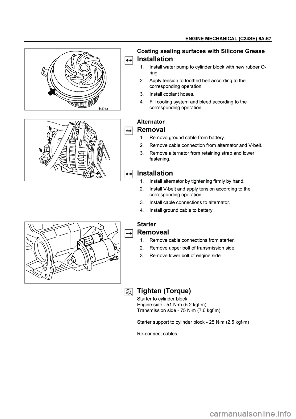
1. Install water pump to cylinder block with new rubber O-
ring.
2. Apply tension to toothed belt according to the
corresponding operation.
3. Install coolant hoses.
4. Fill cooling system and bleed according to the
corresponding operation.
Alternator
Removal
1. Remove ground cable from battery.
2. Remove cable connection from alternator and V-belt.
3. Remove alternator from retaining strap and lower
fastening.
Installation
1. Install alternator by tightening firmly by hand.
2. Install V-belt and apply tension according to the
corresponding operation.
3. Install cable connections to alternator.
4. Install ground cable to battery.
Starter
Removeal
1. Remove cable connections from starter.
2. Remove upper bolt of transmission side.
3. Remove lower bolt of engine side.
Tighten (Torque)
Starter to cylinder block:
Engine side - 51 N�
m (5.2 kgf�
m)
Transmission side - 75 N�
m (7.6 kgf�
m)
Starter support to cylinder block - 25 N�
m (2.5 kgf�
m)
Re-connect cables.
Page 2489 of 4264
ENGINE MECHANICAL (C24SE) 6A-69
FUEL INJECTION SYSTEM
MAP SENSOR
Removal
1. Disconnect the battery cable.
2. Disconnect the electrical connector from the sensor.
3. Remove the mounting bolts securing the sensor to the manifold.
4. Remove the sensor from the intake manifold.
Installation
1. Push MAP sensor into the manifold.
2. Install the mounting bolts and tighten them.
3. Connect electrical connector.
4. Connect the battery cable.
Pressure Regulator
Removal
1. Remove vacuum hose.
2. Remove fuel hoses.
3. Remove pressure regulator.
Installation
1. Install pressure regulator.
2. Install fuel hoses.
3. Install vacuum hoses.
ECM (Engine Control Module)
Removal
(2.4L)
1. Disconnect the ECM connector.
2. Remove the four hex bolts and nuts.
3. Remove the ECM from the ECM bracket on engine.
Page 2517 of 4264
ENGINE COOLING 6B-7
Water Pump
Water Pump and Associated Parts
Legend
1 Water Pump Assembly 2 O-Ring
3 Bolt
2 3 1
Removal
1. Disconnect battery ground cable.
2. Drain coolant.
3. Disconnect radiator hose (on inlet pipe side).
4. Remove timing belt, refer to "Timing Belt" in this manual.
5. Remove water pump assembly.
Inspection
Make necessary repair and parts replacement if extreme wear
or damage is found during inspection. Should any of the
following problems occur, the entire water pump assembly
must be replaced:
Page 2518 of 4264
6B-8 ENGINE COOLING
� Crack in the water pump body
� EC leakage from the seal unit
� Play or abnormal noise in the bearing
� Cracks or corrosion in the impeller
Installation
1. Before installing water pump, coat sealing surface with
silicon grease.
2. Install water pump assembly and tighten bolts to the
specified torque.
Torque: 25 N�
�� �m (2.5 kgf�
�� �m)
3. Timing belt
� Install timing belt, refer to timing belt installation step in
"Timing Belt" in this manual.
4. Connect radiator hose and replenish EC.
5. Connect battery ground cable.