Page 2233 of 4264
3.5L ENGINE DRIVEABILITY AND EMISSIONS 6E-237
Step Action Value (s) Yes No
8
Remove the CKP sensor from the cylinder block and
visually check.
Check for the following conditions.
� Objects sticking the CKP sensor.
� Objects sticking the CKP sensor pluser.
� Gear missing the CKP sensor pluser.
Was the problem found?
- Verify repair Go to Step 9
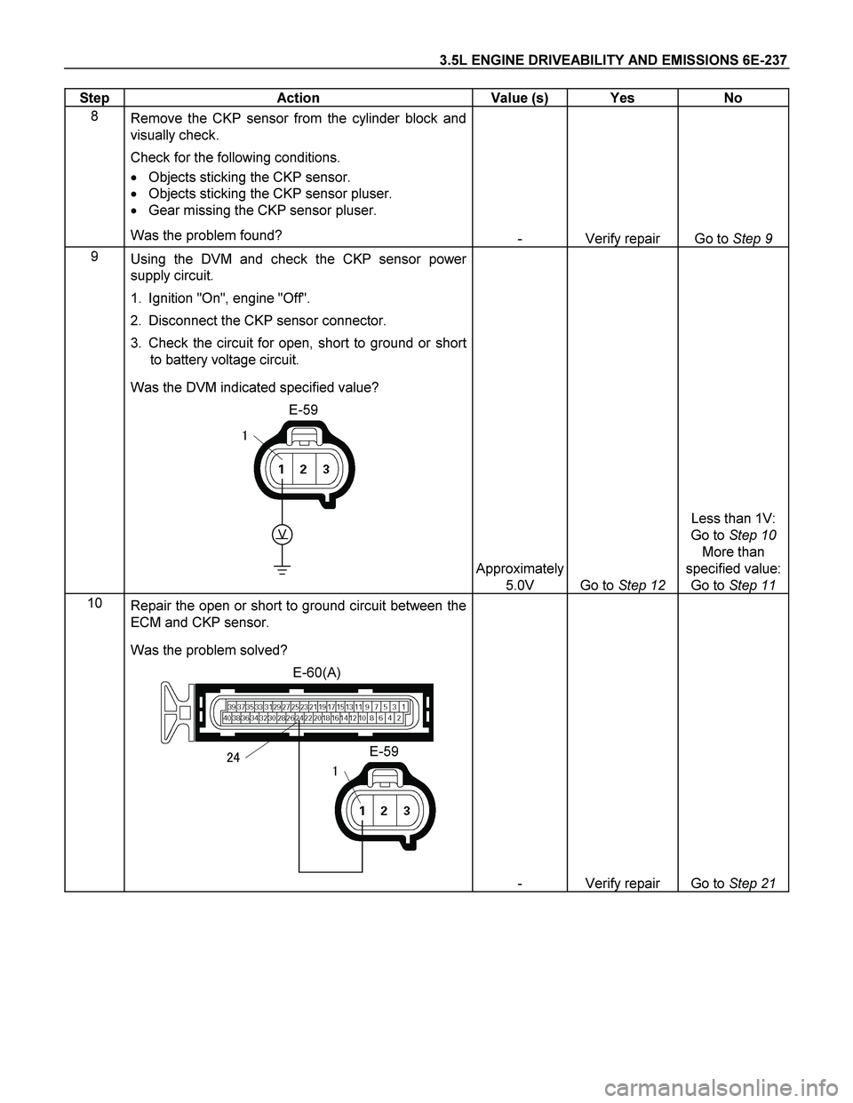
9
Using the DVM and check the CKP sensor power
supply circuit.
1. Ignition "On", engine "Off".
2. Disconnect the CKP sensor connector.
3. Check the circuit for open, short to ground or short
to battery voltage circuit.
Was the DVM indicated specified value?
E-59
V
�
Approximately
5.0V
Go to Step 12
Less than 1V:
Go to Step 10
More than
specified value:
Go to Step 11
10
Repair the open or short to ground circuit between the
ECM and CKP sensor.
Was the problem solved?
E-60(A)
E-59���
- Verify repair Go to Step 21
Page 2234 of 4264
6E-238 3.5L ENGINE DRIVEABILITY AND EMISSIONS
Step Action Value (s) Yes No
11
Repair the short to battery voltage circuit between the
ECM and CKP sensor.
Was the problem solved?
E-60(A)
E-59���
- Verify repair Go to Step 21
12
Using the DVM and check the CKP sensor signal
circuit.
Breaker box is available:
1. Ignition "Off", engine "Off".
2. Install the breaker box as type A (ECM
disconnected).
Refer to 6E-95 page.
3. Disconnect the CKP sensor connector.
4. Check the circuit for open, short to sensor ground
or short to ground circuit.
Was the problem found?
E-59�
�
A23A25
�
Breaker Box
�
Page 2242 of 4264
6E-246 3.5L ENGINE DRIVEABILITY AND EMISSIONS
Step Action Value (s) Yes No
8
1. Ignition "On", engine "Off".
2. Disconnect the CMP sensor connector.
3. Check the circuit for open, short to ground or short
to battery voltage circuit.
Was the DVM indicated specified value?
E-62
V
�
Approximately
5.0V Go to Step 11 Less than 1V:
Go to Step 9
More than
specified value:
Go to Step 10
9
Repair the open, short to sensor gorund or short to
ground circuit between the ECM and CMP sensor.
Was the problem solved?
E-61(B)
E-62
��
�
- Verify repair Go to Step 15
10
Repair the short to battery voltage circuit between the
ECM and CMP sensor.
Was the problem solved?
E-61(B)
E-62
��
�
- Verify repair Go to Step 15
Page 2248 of 4264
6E-252 3.5L ENGINE DRIVEABILITY AND EMISSIONS
Step Action Value (s) Yes No
4
Check for poor/faulty connection at the ignition coil or
ECM connector. If a poor/faulty connection is found,
repair as necessary.
Was the problem found?
E-60(A)
E-61(B)
E-53/E-54/E-55/
E-56/E-57/E-58
E-73/E-74
��
����
�
��
��
�
- Verify repair Go to Step 5
5
Visually check the ignition coil for the affected cylinder.
Was the problem found?
- Go to Step 12 Go to Step 6
6
Using the DVM and check the ignition coil signal
circuit for the affected cylinder.
1. Ignition "On", engine "Off".
2. Disconnect the ignition coil connector for the
affected cylinder.
3. Check the circuit for short to battery voltage circuit.
Was the DVM indicated battery voltage?
E-53/E-54/E-55/
E-56/E-57/E-58
V
�
-
Repair faulty
harness and
verify repair
Go to Step 7
Page 2258 of 4264
 Yes No
10
Using the DVM and check the EGR valve solenoid
signal circuit.
1. Ignition \"Off\", engine \"Off\".
2. Disconne")
6E-262 3.5L ENGINE DRIVEABILITY AND EMISSIONS
Step Action Value (s) Yes No
10
Using the DVM and check the EGR valve solenoid
signal circuit.
1. Ignition "Off", engine "Off".
2. Disconnect the EGR valve connector.
3. Check the circuit for short to battery voltage circuit.
Was the DVM indicated battery voltage?
E-76
V
�
-
Repair faulty
harness and
verify repair
Go to Step 11
11
Substitute a known good EGR valve and recheck.
Was the problem solved?
- Go to Step 12 Go to Step 13
12
Replace the EGR valve.
Was the problem solved?
- Verify repair Go to Step 13
13
Is the ECM programmed with the latest software
release?
If not, download the latest software to the ECM using
the "SPS (Service Programming System)".
Was the problem solved?
- Verify repair Go to Step 14
14
Replace the ECM.
Is the action complete?
IMPORTANT: The replacement ECM must be
programmed. Refer to section of the Service
Programming System (SPS) in this manual. Following
ECM programming, the immobilizer system (if
equipped) must be linked to the ECM. Refer to section
11 “Immobilizer System-ECM replacement” for the
ECM/Immobilizer linking procedure.
- Verify repair -
Page 2274 of 4264
 Yes No
9
Using the DVM and check the purge solenoid valve
signal circuit.
1. Ignition \"On\", engine \"Off\".
2. Disconne")
6E-278 3.5L ENGINE DRIVEABILITY AND EMISSIONS
Step Action Value (s) Yes No
9
Using the DVM and check the purge solenoid valve
signal circuit.
1. Ignition "On", engine "Off".
2. Disconnect the purge solenoid valve connector.
3. Check the circuit for short to battery voltage circuit.
Was the DVM indicated battery voltage?
E-66
V
�
-
Repair faulty
harness and
verify repair
Go to Step 10
10
Substitute a known good purge solenoid valve and
recheck.
Was the problem solved?
- Go to Step 11 Go to Step 12
11
Replace the purge solenoid valve.
Was the problem solved?
- Verify repair Go to Step 12
12
Is the ECM programmed with the latest software
release?
If not, download the latest software to the ECM using
the "SPS (Service Programming System)".
Was the problem solved?
- Verify repair Go to Step 13
13
Replace the ECM.
Is the action complete?
IMPORTANT: The replacement ECM must be
programmed. Refer to section of the Service
Programming System (SPS) in this manual. Following
ECM programming, the immobilizer system (if
equipped) must be linked to the ECM. Refer to section
11 “Immobilizer System-ECM replacement” for the
ECM/Immobilizer linking procedure.
- Verify repair -
Page 2284 of 4264
 P0562 (FLASH CODE 66) SYSTEM
VOLTAGE LOW
Condition For Setting The DTC and Action Taken When The DTC Sets
Flash
Code")
6E-288 3.5L ENGINE DRIVEABILITY AND EMISSIONS
DIAGNOSTIC TROUBLE CODE (DTC) P0562 (FLASH CODE 66) SYSTEM
VOLTAGE LOW
Condition For Setting The DTC and Action Taken When The DTC Sets
Flash
Code Code Type DTC Name DTC Setting Condition Fail-Safe (Back Up)
66 P0562 D System Voltage Low Battery voltage is below 6V for more than 20 seconds. No fail-safe function.
CIRCUIT DESCRIPTION
The engine control module (ECM) monitors the system
voltage on the ignition feed terminals to the ECM.
A
system voltage DTC will set whenever the voltage is
above a calibrated value.
DIAGNOSTIC AIDS
If the DTC sets when an accessory is operated, check
for a poor connection or defective accessory.
Diagnostic Trouble Code (DTC) P0562 (Flash Code 66)
System Voltage Low
Step Action Value (s) Yes No
1
Was the "On-Board Diagnostic (OBD) System Check"
performed?
- Go to Step 2 Go to On Board
Diagnostic (OBD)
System Check
2
1. Connect the Tech 2.
2. Review and record the failure information.
3. Select "F0: Read DTC Infor By Priority" in "F0:
Diagnostic Trouble Code".
Is the DTC P0562 stored as "Present Failure"?
- Go to Step 3 Refer to
Diagnostic Aids
and Go to Step 3
3
1. Using the Tech2, ignition "On" and engine "Off".
2. Select "Clear DTC Information" with the Tech2 and
clear the DTC information.
3. Operate the vehicle and monitor the "F5: Failed
This Ignition" in "F2: DTC Information"
Was the DTC P0562 stored in this ignition cycle?
- Go to Step 4 Refer to
Diagnostic Aids
and Go to Step 4
4
1. Using the Tech 2, ignition "On" and engine "On".
2. Monitor the "Ignition Voltage" in the data display.
3. Load the electrical system by turning on the
headlights, etc..
Does the Tech 2 indicate enough ignition voltage?
10 – 14.5V Go to Step 6 Go to Step 5
5
Using the DVM and check the battery voltage at the
battery terminal.
Does the tester indicate enough battery voltage?
10 – 14.5V Go to Step 6 Check the
charging system,
charge or replace
the battery
Page 2287 of 4264
 P0563 (FLASH CODE 66)
SYSTEM VOLTAGE HIGH
Condition For Setting The DTC and Action Taken When The DTC Sets
Flash
Cod")
3.5L ENGINE DRIVEABILITY AND EMISSIONS 6E-291
DIAGNOSTIC TROUBLE CODE (DTC) P0563 (FLASH CODE 66)
SYSTEM VOLTAGE HIGH
Condition For Setting The DTC and Action Taken When The DTC Sets
Flash
Code Code Type DTC Name DTC Setting Condition Fail-Safe (Back Up)
66 P0563 A System Voltage High Battery voltage is above 16V for more than 20 seconds. No fail-safe function.
CIRCUIT DESCRIPTION
The engine control module (ECM) monitors the system
voltage on the ignition feed terminals to the ECM.
A
system voltage DTC will set whenever the voltage is
above a calibrated value.
DIAGNOSTIC AIDS
If the DTC sets when an accessory is operated, check
for a poor connection or defective accessory.
Diagnostic Trouble Code (DTC) P0563 (Flash Code 66)
System Voltage High
Step Action Value (s) Yes No
1
Was the "On-Board Diagnostic (OBD) System Check"
performed?
- Go to Step 2 Go to On Board
Diagnostic
(OBD) System
Check
2
1. Connect the Tech 2.
2. Review and record the failure information.
3. Select "F0: Read DTC Infor By Priority" in "F0:
Diagnostic Trouble Code".
Is the DTC P0563 stored as "Present Failure"?
- Go to Step 3 Refer to
Diagnostic Aids
and Go to Step
3
3
1. Using the Tech2, ignition "On" and engine "Off".
2. Select "Clear DTC Information" with the Tech2 and
clear the DTC information.
3. Operate the vehicle and monitor the "F5: Failed This
Ignition" in "F2: DTC Information"
Was the DTC P0563 stored in this ignition cycle?
- Go to Step 4 Refer to
Diagnostic Aids
and Go to Step
4
4
1. Using the Tech 2, ignition "On" and engine "On".
2. Monitor the "Ignition Voltage" in the data display.
3. Load the electrical system by turning on the
headlights, etc..
Does the Tech 2 indicate correct ignition voltage?
Less than 16VGo to Step 5 Check the
charging
system and Go
to Step 5
5
Is the battery jamp start cable incorrectly connecting?
- Verify
procedure Go to Step 6
6
Is the ECM programmed with the latest software
release?
If not, download the latest software to the ECM using the
"SPS (Service Programming System)".
Was the problem solved?
- Verify repair Go to Step 7
 Yes No
11
Repair the short to battery voltage circuit between the
ECM and CKP sensor.
Was the problem solved?
E-60(A)
E-")
 Yes No
8
1. Ignition \"On\", engine \"Off\".
2. Disconnect the CMP sensor connector.
3. Check the circuit for open, short")
 Yes No
4
Check for poor/faulty connection at the ignition coil or
ECM connector. If a poor/faulty connection is found,
rep")