Page 832 of 4264

8A-174 ELECTRICAL-BODY AND CHASSIS
Installation
Follow the removal procedure in the reverse order to install the
rear combination light.
Pay close attention to the important points mentioned in the
following paragraphs.
Bulb
Be absolutely sure that each bulb is correctly installed.
This will prevent a poor contact and an open circuit.
SIDE TURN LIGHT
Removal
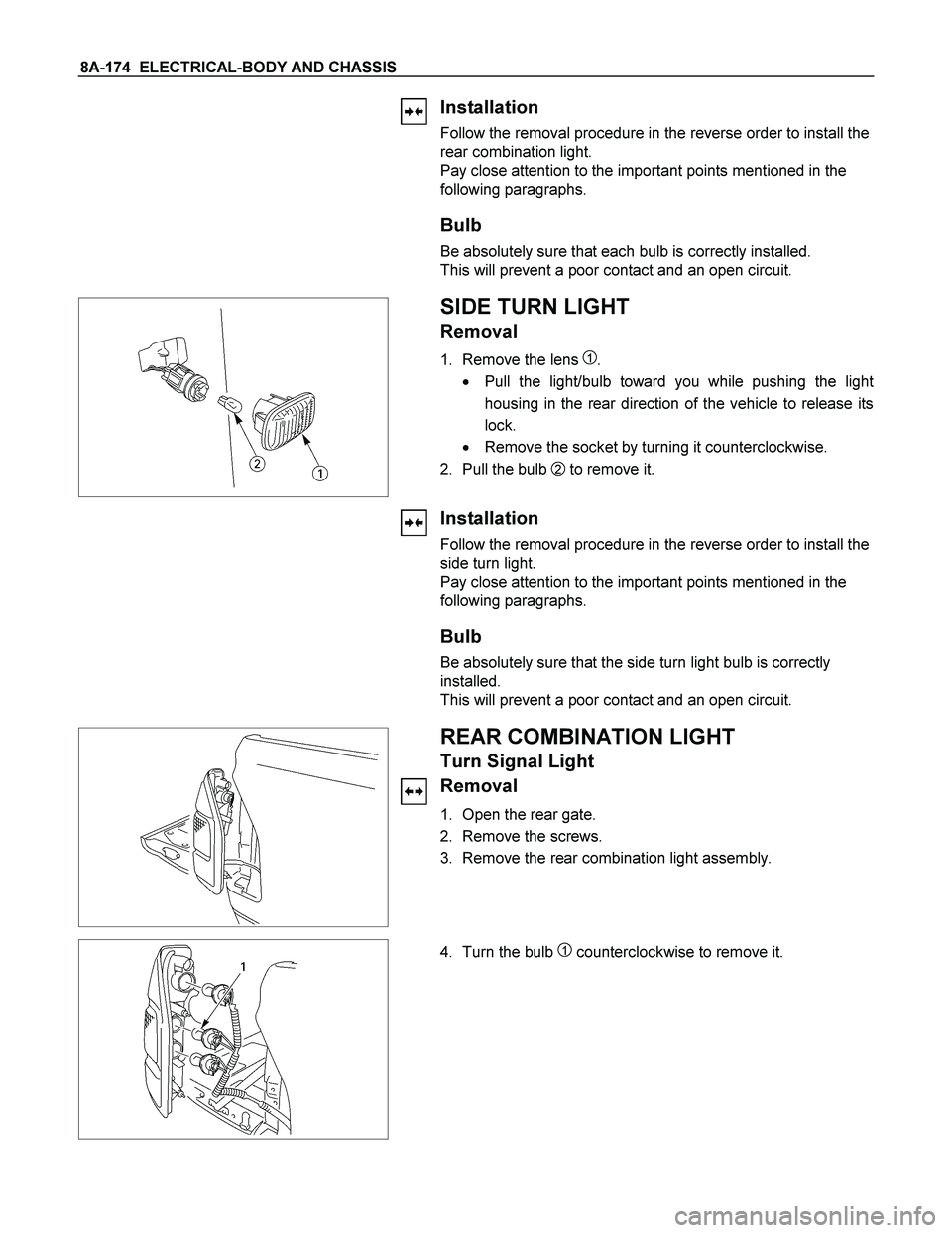
1. Remove the lens 1.
� Pull the light/bulb toward you while pushing the ligh
t
housing in the rear direction of the vehicle to release its
lock.
� Remove the socket by turning it counterclockwise.
2. Pull the bulb
2 to remove it.
Installation
Follow the removal procedure in the reverse order to install the
side turn light.
Pay close attention to the important points mentioned in the
following paragraphs.
Bulb
Be absolutely sure that the side turn light bulb is correctly
installed.
This will prevent a poor contact and an open circuit.
REAR COMBINATION LIGHT
Turn Signal Light
Removal
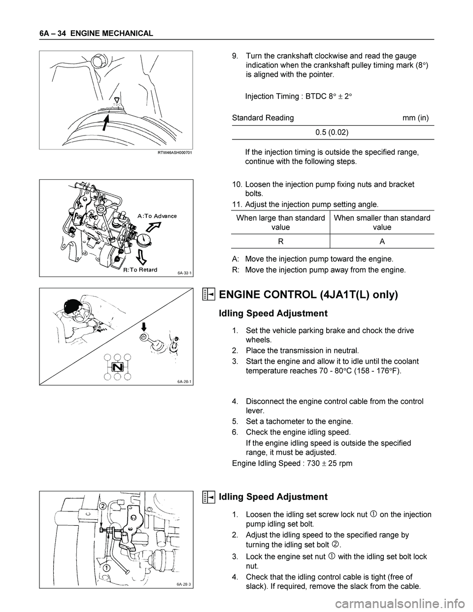
1. Open the rear gate.
2. Remove the screws.
3. Remove the rear combination light assembly.
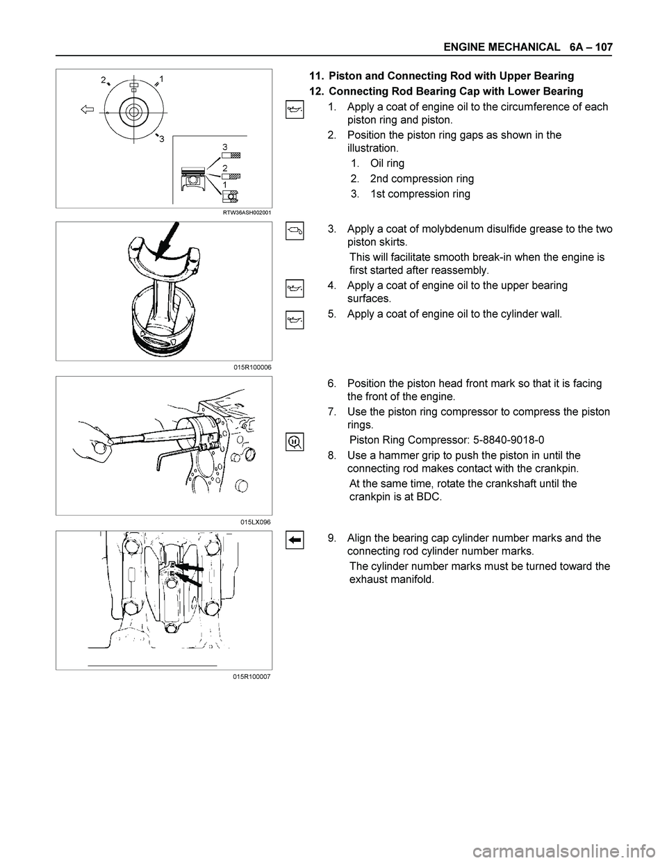
4. Turn the bulb 1 counterclockwise to remove it.
Page 1015 of 4264
ELECTRICAL-BODY AND CHASSIS 8A-357
(5) If there is a place where the voltage suddenly changes to
0V, there is a broken wire between there and the powe
r
side.
(6) Move the tester probe from the position where the voltage
changes to 0V toward the power side and find where the
voltage suddenly increases.
REPAIR OF BROKEN HEAT WIRE
(1) Clean broken wire tips with white gasoline.
(2) Place masking tape along both sides of wire to be repaired.
(3) Thoroughly mix the repair agent (Dupont paste No. 4817 or
equivalent).
(4) Using a fine tip brush, apply a small amount to the wire.
(5) After a couple of minutes, remove the masking tape.
(6) Allow to stand at least 24 hours.
Page 1174 of 4264

6A – 34 ENGINE MECHANICAL
RTW46ASH000701
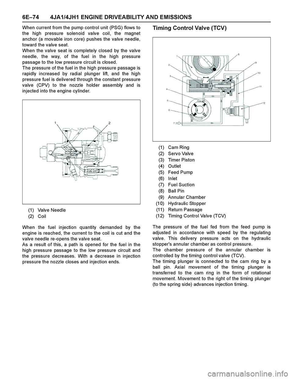
9. Turn the crankshaft clockwise and read the gauge
indication when the crankshaft pulley timing mark (8�)
is aligned with the pointer.
Injection Timing : BTDC 8� � 2�
Standard Reading mm (in)
0.5 (0.02)
If the injection timing is outside the specified range,
continue with the following steps.
10. Loosen the injection pump fixing nuts and bracket
bolts.
11. Adjust the injection pump setting angle.
When large than standard
value When smaller than standard
value
R A
A: Move the injection pump toward the engine.
R: Move the injection pump away from the engine.
ENGINE CONTROL (4JA1T(L) only)
Idling Speed Adjustment
1. Set the vehicle parking brake and chock the drive
wheels.
2. Place the transmission in neutral.
3. Start the engine and allow it to idle until the coolant
temperature reaches 70 - 80�C (158 - 176�F).
4. Disconnect the engine control cable from the control
lever.
5. Set a tachometer to the engine.
6. Check the engine idling speed.
If the engine idling speed is outside the specified
range, it must be adjusted.
Engine Idling Speed : 730 � 25 rpm
Idling Speed Adjustment
1. Loosen the idling set screw lock nut � on the injection
pump idling set bolt.
2. Adjust the idling speed to the specified range by
turning the idling set bolt
�.
3. Lock the engine set nut
� with the idling set bolt lock
nut.
4. Check that the idling control cable is tight (free of
slack). If required, remove the slack from the cable.
Page 1192 of 4264
6A – 52 ENGINE MECHANICAL
RTW36ASH000801
Idler Gear "A" End Play Measurement
Insert a feeler gauge between the idler gear and the thrust
collar to measure the gap and determine the idler gear
end play.
If the measured value exceeds the specified limit, the
thrust collar must be replaced.
Idler Gear End Play mm (in)
Standard Limit
0.07 (0.0028) 0.2 (0.0079)
4JA1T(L)
040R300009
14. Idle Gear Shaft
15. Crankshaft Timing Gear
4JA1TC/4JH1TC RTW36ASH001301
16. Injection Pump
1. Remove the injection pump cover (4JA1TC/4JH1TC
only).
2. Remove the injection pump bracket.
3. Pull the injection pump along with the injection pump
timing gear free toward the rear of the engine.
NOTE:
Plug the injection pump delivery ports with the caps to
prevent the entry of foreign material.
17. Flywheel
Loosen the flywheel bolts in numerical order a little at a
time.
Use the gear stoper to stop the flywheel gear.
Gear stoper: 5-8840-0214-0
18. Crank Case
19. Oil Pump With Oil Pipe
015RY00001
Page 1247 of 4264

ENGINE MECHANICAL 6A – 107
RTW36ASH002001
11. Piston and Connecting Rod with Upper Bearing
12. Connecting Rod Bearing Cap with Lower Bearing
1. Apply a coat of engine oil to the circumference of each
piston ring and piston.
2. Position the piston ring gaps as shown in the
illustration.
1. Oil ring
2. 2nd compression ring
3. 1st compression ring
3. Apply a coat of molybdenum disulfide grease to the two
piston skirts.
This will facilitate smooth break-in when the engine is
first started after reassembly.
4. Apply a coat of engine oil to the upper bearing
surfaces.
5. Apply a coat of engine oil to the cylinder wall.
6. Position the piston head front mark so that it is facing
the front of the engine.
7. Use the piston ring compressor to compress the piston
rings.
Piston Ring Compressor: 5-8840-9018-0
8. Use a hammer grip to push the piston in until the
connecting rod makes contact with the crankpin.
At the same time, rotate the crankshaft until the
crankpin is at BDC.
9. Align the bearing cap cylinder number marks and the
connecting rod cylinder number marks.
The cylinder number marks must be turned toward the
exhaust manifold.
015LX096
015R100007015R100006
Page 1346 of 4264
6D – 8 ENGINE ELECTRICAL
033RY00009
Cooling Fan Drive Belt
1. Hold the generator toward the engine.
2. Install the fan belt to the three pulleys.
1 Crankshaft pulley
2 Generator pulley
3 Cooling fan drive pulley
3. Adjust the fan belt tension
Fan belt tension is adjusted by moving the generator.
Depress the drive belt mid-portion with a 98N (10
kg/22 Ib) force.
Cooling Fan Drive Belt Deflection mm (in)
New belt 4 - 7 (0.16 - 0.28)
Reuse belt 6 - 9 (0.24 - 0.35)
4. Tighten the adjusting plate bolts to the specified
torque.
Adjusting Plate Bolt N·m (kg·m/lb·ft)
19 (1.9/14)
5. Reconnect the battery cable to the battery.
Page 1446 of 4264

6E–74 4JA1/4JH1 ENGINE DRIVEABILITY AND EMISSIONS
When current from the pump control unit (PSG) flows to
the high pressure solenoid valve coil, the magnet
anchor (a movable iron core) pushes the valve needle,
toward the valve seat.
When the valve seat is completely closed by the valve
needle, the way, of the fuel in the high pressure
passage to the low pressure circuit is closed.
The pressure of the fuel in the high pressure passage is
rapidly increased by radial plunger lift, and the high
pressure fuel is delivered through the constant pressure
valve (CPV) to the nozzle holder assembly and is
injected into the engine cylinder.
When the fuel injection quantity demanded by the
engine is reached, the current to the coil is cut and the
valve needle re-opens the valve seat.
As a result of this, a path is opened for the fuel in the
high pressure passage to the low pressure circuit and
the pressure decreases. With a decrease in injection
pressure the nozzle closes and injection ends.Timing Control Valve (TCV)
The pressure of the fuel fed from the feed pump is
adjusted in accordance with speed by the regulating
valve. This delivery pressure acts on the hydraulic
stopper's annular chamber as control pressure.
The chamber pressure of the annular chamber is
controlled by the timing control valve (TCV).
The timing plunger is connected to the cam ring by a
ball pin. Ax ial movement of the timing plunger is
transferred to the cam ring in the form of rotational
movement. Movement to the right of the timing plunger
(to the spring side) advances injection timing. (1) Valve Needle
(2) Coil
(1) Cam Ring
(2) Servo Valve
(3) Timer Piston
(4) Outlet
(5) Feed Pump
(6) Inlet
(7) Fuel Suction
(8) Ball Pin
(9) Annular Chamber
(10) Hydraulic Stopper
(11) Return Passage
(12) Timing Control Valve (TCV)
Page 1793 of 4264
4JA1/4JH1 ENGINE DRIVEABILITY AND EMISSIONS 6E–421
EGR EVRV (Electrical Vacuum
Regulating Valve)
Location
Back of the air cleaner case.
Removal Procedure
1. Disconenct the negative battery cable.
2. Disconnect a EVRV connector from the EVRV.
3. Disconnect two hoses from the EVRV.
4. Loosen two bolts and remove the EVRV from the
bracket.
Installation Procedure
1. Tighten the purge solenoid by tow bolts.
2. Connect a connector to the EVRV.
3. Connect two hoses to the EVRV.
4. Connect the negative battery cable.
NOTE: Verify any DTCs (diagnosis Trouble Code) are
not stored after replacement.
Verify proper connection of two hoses.