Page 2846 of 4264

6E–270 ENGINE DRIVEABILITY AND EMISSIONS
FUEL PRESSURE RELIEF
Caution: To reduce the risk of fire and personal
injury, it is necessary to relieve the fuel system
pressure before servicing the fuel system
components.
Caution: After relieving the fuel system pressure, a
small amount of fuel may be released when
servicing fuel lines or connections. Reduce the
chance of personal injury by covering the fuel line
fitting with a short towel before disconnecting the
fittings. The towel will absorb any fuel that may leak
out. When the disconnect is completed, place the
towel in an approved container.
1. Remove the fuel filler cap.
2. Remove the fuel pump relay from the underhood
relay box .
3. Start the engine and allow it to stall.
4. Crank the engine for about 30 seconds.
5. Disconnect the negative battery cable.
FUEL RAIL ASSEMBLY
Removal Procedure
NOTE:
Use care when removing the fuel rail assembly in
order to prevent damage to the injector al connector
terminal and the injector spray tips.
Fitting should be capped and holes plugged during
servicing to prevent dirt and other contaminants from
entering open lines and passage.
Important: An eight-digit identification number is
stamped on side of the fuel injector. Refer to this
number when you service the fuel rail or when a
replacement part is required.
1. Disconnect 4 injector connectors.
2. Lift side-clip up on the fuel rail.
3. Disconnect fuel pressure regulator hose.
4. Disconnect wiring harness from the bands on the
fuel rail.
5. Remove the intake pipe.
6. Loosen flare nut.
A. Lift up the injectors carefully to separate them
from intake manifold.
B. Lift up the fuel rail with injectors as assembly.
Do not separate the fuel injectors from fuel rail.
C. If an injector become separated from fuel rail,
injector backup O-ring and injector retainer clip
must be replaced.
D. Drain residual fuel from fuel rail into an
approved container.
7. If removal of fuel pressure regulator is necessary,
Refer to Fuel Pressure Regulator Removal
Procedure.
Page 2849 of 4264
. Refer to Fuel Rail Installation
Procedure.
Tighten the flare nut to 27 - 33 N·m (2.")
ENGINE DRIVEABILITY AND EMISSIONS 6E–273
7. Install fuel rail assembly. Tighten the nuts to 19 N·m
(1.9 kgf·m). Refer to Fuel Rail Installation
Procedure.
Tighten the flare nut to 27 - 33 N·m (2.8 - 3.4 kgf·m).
8. Connect the negative battery cable.FUEL PRESSURE REGULATOR
Removal Procedure
Caution: To reduce the risk of fire and personal
injury, it is necessary to relieve the fuel system
pressure before servicing the fuel system
components.
Caution: After relieving the fuel system pressure, a
small amount of fuel may be released when
servicing fuel lines or connections. Reduce the
chance of personal injury by covering the fuel line
fitting with a shop towel before disconnecting the
fittings. The towel will absorb any fuel that may leak
out. When the disconnect is completed, place the
towel in an approved container.
NOTE: Compressed air must never be used to test or
clean a fuel pressure regulator, as damage to the fuel
pressure regulator may occur.
NOTE: To prevent damage to the fuel pressure
regulator, do not immerse the pressure regulator in
solvent.
Removal Procedure
1. Depressurize the fuel system. Refer to Fuel
Pressure Relief Procedure.
2. Disconnect the negative battery cable.
3. Remove the fuel pump relay.
4. Disconnect the vacuum line form fuel pressure
regulator.
Page 2937 of 4264
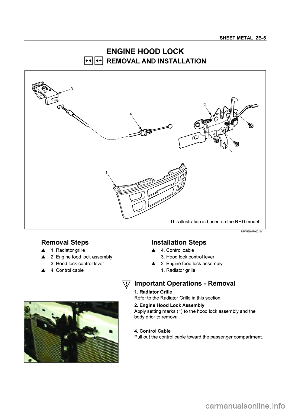
SHEET METAL 2B-5
ENGINE HOOD LOCK
REMOVAL AND INSTALLATION
This illustration is based on the RHD model.
RTW42BMF000101
Removal Steps
Installation Steps
�
1. Radiator grille
�
4. Control cable
�
2. Engine food lock assembly
3. Hood lock control lever
3. Hood lock control lever
�
2. Engine food lock assembly
�
4. Control cable
1. Radiator grille
Important Operations - Removal
1. Radiator Grille
Refer to the Radiator Grille in this section.
2. Engine Hood Lock Assembly
Apply setting marks (1) to the hood lock assembly and the
body prior to removal.
4. Control Cable
Pull out the control cable toward the passenger compartment.
Page 2977 of 4264
GENERAL INFORMATION 0A-5
7. Measurement criteria are defined by the terms "standard" and "limit".
A measurement falling within the "standard" range indicates that the applicable part or parts are serviceable.
"Limit" is an absolute value.
A measurement falling outside the "limit" indicates that the applicable part or parts must be repaired or replaced.
8. Components are parts are listed in the singular form throughout the Workshop Manual.
9. The following directional criteria are used throughout the Workshop Manual:
Front:
The cooling fan side of the engine.
Right:
The right-hand side of the engine viewed from the flywheel.
Left:
The left-hand side of the engine viewed from the flywheel.
Rear:
The flywheel side of the engine.
Cylinder numbers are counted from the front of the engine towards the rear.
The engine's rotation is clockwise viewed from the front of the engine.
Page 2999 of 4264

Severe driving conditions
A : Repeated short trips
G : Gasoline engine
B : Driving on rough")
MAINTENANCE AND LUBRICATION 0B-11
SEVERE CONDITIONS MAINTENANCE SCHEDULE (For GENERAL EXPORT)
Severe driving conditions
A : Repeated short trips
G : Gasoline engine
B : Driving on rough roads
4JA1-T : 4JA1-T Diesel engine
C : Driving on dusty roads
4JA1-TC : 4JA1-TC Diesel engine
D : Driving in extremely cold weather and/or on salted roads
4JH : 4JH1-TC Diesel engine
E : Towing trailer or climbing mountain frequently
D�: Diesel engine
MT : Manual transmission
AT : Automatic transmission
4WD��Four wheel drive
�
Condition
A B C D E A+D
Engine oil G : Change every 5,000 km (3,000 miles) or 3 month4JA1-T : Change every 2,500 km (1,500 miles) 4JA1-TC : Change every 5,000 km (3,000 miles) 4JH : Change every 7,500 km (4,500 miles) �
�
G Replace every 5,000 km (3,000 miles) or 3 month
�
�Engine oil filter
D Replace every 5,000 km (3,000 miles)
�
�
Exhaust system Inspect every 5,000 km (3,000 miles)
��
�
Air cleaner element Replace every 20,000 km (12,000 miles) D : Inspect every 2,500 km (1,500 miles)
�
Steering system for looseness
or damage Inspect every 5,000 km (3,000 miles)
�
Universal joints and sleeves Inspect for wear and lubricate every 5,000 km (3,000
miles)
� �
Transmission or transfer case
oil MT Change every 20,000 km (12,000 miles)
after changing at initial 10,000 km (6,000 miles)
�
AT Transmission:
Change every 20,000 km (12,000 miles) �� �
��
4WD Transfer:
Change every 20,000 km (12,000 miles)
�
Differential oil Change every 20,000 km (12,000 miles)
after changing at initial 10,000 km (6,000 miles)
�
Front brake pads and discs Inspect every 5,000 km (3,000 miles)
�� �
Rear brake lining and drum
wear Inspect every 5,000 km (3,000 miles)
�� �
�
Interval Item
Page 3000 of 4264

�
Severe driving conditions
4JA1-TC : 4JA1-TC Diesel engine
A: Repeated short trips
4JH : 4JH1-TC Diesel e")
0B-12 MAINTENANCE AND LUBRICATION
SEVERE CONDITIONS MAINTENANCE SCHEDULE (For EUROPE)
�
Severe driving conditions
4JA1-TC : 4JA1-TC Diesel engine
A: Repeated short trips
4JH : 4JH1-TC Diesel engine
B: Driving on rough roads
D : Diesel engine
C: Driving on dusty roads
MT : Manual transmission
D: Driving in extremely cold weather and/or on salted roads
AT : Automatic transmission
E: Towing trailer or climbing mountein frequently
4WD : Four wheel drive
�
Condition
Item Interval
A B C D A+D
Engine oil 4JH : Change every 5,000 km (3,000 miles) 4JA1-TC : Change every 7,500 km (4,500 miles)
�
�Engine oil filter 4JH : Replace every 5,000 km (3,000 miles) 4JA1-TC : Replace every 7,5000 km (4,500 miles)
�
�
Exhaust pipes and mounting Inspect every 10,000 km (6,000 miles)
� �
�
Air cleaner element Replace every 20,000 km (12,000 miles)
�
Steering system for looseness or
damage Inspect every 5,000 km (3,000 miles)
�
Universal joints and sleeves Inspect for wear and lubricate every 10,000 km (6,000 miles)
� �
Transmission or transmission
with transfer case oil MT Change every 30,000 km (18,000 miles)
after changing at initial 10,000 km (6,000 miles)
�
AT
Transmission:
Inspection every 20,000 km (12,000 miles) � � �
�
4WD Transfer:
Change every 30,000 km (18,000 miles)
After changing at initial 10,000 km (6,000 miles)
�
Differential oil Change every 20,000 km (12,000 miles)
after changing at initial 10,000 km (6,000 miles)
�
Front brake pads and discs Inspect every 5,000 km (3,000 miles)
� � �
Rear brake lining and drum wear Inspect every 5,000 km (3,000 miles)
� � �
�
�
Page 3126 of 4264
7B-8 MSG MODEL
Exhaust Pipe
1. Remove the exhaust pipe bracket from the transmission
case.
2. Remove the exhaust pipe.
Rear Propeller Shaft (Single Shaft Type)
1. Remove the propeller shaft flange yoke at the drive pinion
side
1.
2. Remove the propeller shaft from the transmission main
shaft spline
2.
Rear Propeller Shaft (Dual Shaft Type)
1. Apply setting marks to the 2nd propeller shaft flange yoke.
This will prevent mispositioning during the installation
procedure.
2. Remove the 2nd propeller shaft flange yoke bolts at the
drive pinion side
1.
3. Remove the center bearing retainer bolts
2 .
4. Remove the 1st propeller shaft with the center bearing and
the 2nd propeller shaft.
Pull the 1st propeller shaft toward the rear of the vehicle
until the spline yoke is free of the transmission main shaft.
Harness Connector
Disconnect the back up light switch connector and the
speedometer sensor connector.
Slave Cylinder
Remove the slave cylinder from the transmission case.
Page 3128 of 4264
7B-10 MSG MODEL
3) Manually move the transmission as far as possible toward
the rear of the vehicle (into the space between the No.3
crossmember
3 and the floor panel 4 .
4) Lower the clutch housing end of the transmission toward the
transmission jack.
The rear of the transmission is supported by the No.3
crossmember at this time.
5) Firmly grasp the transmission rear cover (1st mechanic).
Raise the transmission jack toward the transmission (2nd
mechanic).
Carefully lower the transmission onto the transmission jack.
The transmission must be centered on the transmission
jack.
8. Carefully pull the transmission jack with the transmission
from beneath the vehicle.


1. Remove the p")
 Manually move the transmission as far as possible toward
the rear of the vehicle (into the space between the No.3
crossmember
3 and the floor panel 4 .
4) Lower the cl")