Page 3795 of 4264
ON-VEHICLE SERVICE (AW30 –40LE) 7A3-39
Installation
To install, follow the removal steps in reverse order
noting the following point;
1. Reinstall the parts removed with the valve bod
y
assembly to their assigned positions in the
transmission case (check valve assembly, C0
accumulator pistons, etc). Install the valve bod
y
assembly to the transmission case.
Refer to REASSEMBLY OF MAJO
R
COMPONENTS (2).
2. Solenoid clamp bolt
Torque : 7 N �
��
�
m (61 Ib in)
3. Valve body fixing bolts
Each bolt location and length (mm) is indicated in
the figure.
Torque : 10 N �
��
�
m (87 Ib in)
NOTE: Tighten the bolts toward outside equally.
244R200078
4. Oil strainer fixing bolts
Torque : 10 N �
��
�
m (87 Ib in)
5. Oil pan fixing bolts
Torque : 8 N �
��
�
m (69 Ib in)
Page 3840 of 4264
7A4–32 UNIT REPAIR (AW30–40LE)
If the values are nonstandard, check for an improper
installation.
24 8RY 0 000 4
23. Coat the race with petroleum jelly and install it onto
the overdrive support assembly.
Race diameter (Reference)
25 2RY 0 000 7
24. Aim the bolt and oil holes of the overdrive support
toward the valve hole side, and align them with the
bolt hole of the transmission case and insert the
overdrive support.
25 2RY 0 0005
25. Using snap ring pliers, install the snap ring as
shown in the figure.
25 2RY 0 0008
Inside Outside
Race 36.7 mm (1.44 in) 50.8 mm (2.00 in)
Page 4154 of 4264

7A3-2 ON-VEHICLE SERVICE (JR405E)
DESCRIPTION
Before performing on-vehicle service on the automatic
transmission, check that the engine idling speed and
general engine condition are normal.
AUTOMATIC TRANSMISSION FLUID (ATF)
Inspect
Remove the transmission dipstick to check the condition
of the ATF.
Clean the dipstick and look for gum or varnish.
Gum or varnish indicate scorching of the clutch band
and other parts.
The transmission control module, the transmission unit,
and the vehicle must be carefully checked if gum or
varnish is present.
ATF LEVEL
Inspect
Hot Level
1. Warm up the engine and the transmission by driving
the vehicle on the road so that the temperature
reaches around 80�C (176�F).
Do not turn the engine off.
2. Park the vehicle on a level surface.
3. Apply the parking brake firmly.
4. Let the engine run at idle.
Move the select lever slowly through all the gea
r
ranges.
Stop in each gear range just long enough for the
transmission to engage.
5. Return the select lever to either “P” or “N”.
C07RW009
6. Remove the ATF level dipstick.
7. Wipe the dipstick clean with a paper towel.
8. Reinsert the dipstick and wait several seconds.
9. Remove the dipstick.
The ATF level should be inside the “H” range on the
dipstick.
242R300001
If the ATF level is below the “H” range, ATF must be
added.
Page 4155 of 4264

ON-VEHICLE SERVICE (JR405E) 7A3-3
Cold Level
The vehicle must not have been driven so that the
temperature reaches around 20�C (68�F) before the
cold level check is made.
1. Park the vehicle on a level surface.
2. Apply the parking brake firmly.
3. Start the engine and allow it to warm up.
The engine coolant temperature gauge needle
should be midway between the “C” mark and “H”
mark.
4. Let the engine run at idle.
Move the select lever slowly through all the gea
r
ranges.
Stop in each range just long enough for the
transmission to engage.
5. Return the select lever either “P” or “N”.
6. Remove the ATF level dipstick.
7. Wipe the dipstick clean with a paper towel.
8. Reinsert the dipstick and wait several seconds.
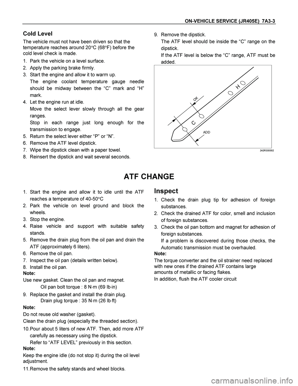
9. Remove the dipstick.
The ATF level should be inside the “C”range on the
dipstick.
If the ATF level is below the “C” range, ATF must be
added.
242R300002
ATF CHANGE
1. Start the engine and allow it to idle until the ATF
reaches a temperature of 40-50�C
2. Park the vehicle on level ground and block the
wheels.
3. Stop the engine.
4. Raise vehicle and support with suitable safety
stands.
5. Remove the drain plug from the oil pan and drain the
ATF (approximately 6 liters).
6. Remove the oil pan.
7. Inspect the oil pan (details written below).
8. Install the oil pan.
Note:
Use new gasket. Clean the oil pan and magnet.
Oil pan bolt torque : 8 N�m (69 lb�in)
9. Replace the gasket and install the drain plug.
Drain plug torque : 35 N�m (26 lb�ft)
Note:
Do not reuse old washer (gasket).
Clean the drain plug (especially the threaded section).
10. Pour about 5 liters of new ATF. Then, add more ATF
carefully as necessary using the dipstick.
Refer to “ATF LEVEL” previously in this section.
Note:
Keep the engine idle (do not stop it) during the oil level
adjustment.
11. Remove the safety stands and wheel blocks. Inspect
1. Check the drain plug tip for adhesion of foreign
substances.
2. Check the drained ATF for color, smell and inclusion
of foreign substances.
3. Check the oil pan bottom and magnet for adhesion o
f
foreign substances.
If a problem is discovered during those checks, the
Automatic transmission must be overhauled.
Note:
The torque converter and the oil strainer need replaced
with new ones if the drained ATF contains large
amounts of metallic or facing flakes.
In addition, flush the ATF cooler circuit
Page 4166 of 4264

7A3-14 ON-VEHICLE SERVICE (JR405E)
Install or Connect
1. Install the shift cable toward the inside of the cabin
from the bottom of the vehicle.
2. Push the shift cable into the select lever base.
3. Connect the shift cable to the select lever.
4. Fix the shift cable to the bracket.
Install the clip on the marking of shift cable.
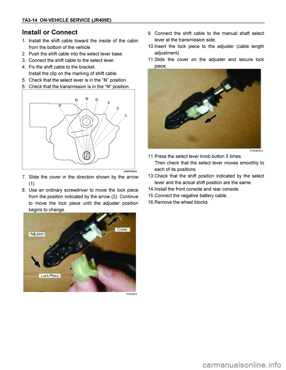
5. Check that the select lever is in the “N” position.
6. Check that the transmission is in the “N” position.
249R300002
7. Slide the cover in the direction shown by the arrow
(1).
8. Use an ordinary screwdriver to move the lock piece
from the position indicated by the arrow (2). Continue
to move the lock piece until the adjuster position
begins to change.
P1010012
9. Connect the shift cable to the manual shaft selec
t
lever at the transmission side.
10. Insert the lock piece to the adjuster (cable length
adjustment).
11. Slide the cover on the adjuster and secure lock
piece.
P1010016-2
11. Press the select lever knob button 5 times.
Then check that the select lever moves smoothly to
each of its positions.
13. Check that the shift position indicated by the selec
t
lever and the actual shift position are the same.
14. Install the front console and rear console.
15. Connect the negative battery cable.
16. Remove the wheel blocks.