Page 1140 of 4264
 Yes No
1 Was “Visual/Physical Check\" performed.
—
Go to Step 2 Go t")
6 – 20 TROUBLESHOOTING
15-3 Starter motor continues to run after the starter switch is turned off
Step Action Value(s) Yes No
1 Was “Visual/Physical Check" performed.
—
Go to Step 2 Go to
visual/physical
check
2 Inspect the magnetic switch contact point.
Was the contact point seized? — Repair or
replace the
magnetic
switch. Go to Step 3
3 Inspect the starter switch.
Was the starter switch defective? — Replace the
starter switch. Go to Step 4
4 Are any DTC stored? — Go to indicated
DTC. Solved
15-4 Excessive commutator sparking
Step Action Value(s) Yes No
1 Was “Visual/Physical Check" performed.
—
Go to Step 2 Go to
visual/physical
check
2 Inspect the contact condition between the brush and
the commutator.
Was the brush and the commutator contact
intermittent? — Replace the
brush or repair
the
commutator. Go to Step 3
3 Was there the slag accumulation on the contact
face? — Clean the
contact face or
replace the
brush. Go to Step 4
4 Was the brush holder loose? — Repair the
brush holder Go to Step 5
5 Inspect the commutator.
Was there excessive wear or pitting? — Repair or
replace the
commutator. Go to Step 6
6 Was there loose the solder on the commutator? — Clean and
repair Go to Step 7
7 Inspect the armature shaft.
Was the run-out of armature shaft outside the
standard value due to worn bearing ? —
Replace the
bearing Go to Step 8
8 Are any DTC stored? — Go to indicated
DTC. Solved
Page 1166 of 4264

6A – 26 ENGINE MECHANICAL
041RY00011
Draining Procedure
The indicator light will come on when the water level in the
water separator exceeds the specified level.
Drain the water and foreign material from the water
separator (inside chassis frame) with the following
procedure.
1. Place the drain pan under the drain plug.
2. Loosen the drain plug and drain water.
3. After draining the water, tighten the drain plug.
4. Operate the priming pump on the fuel filter several
times and check for fuel leakage.
5. Check the water separator indicator light. It should be
off.
Except EURO III model
RTW46ASH002901
For EURO III model
RTW46ASH000501
Air Bleeding
1. Operate the priming pump until strong resistance is
felt.
2. Wait 1 minute, and operate the priming pump until
strong resistance is felt.
3. Once more wait, and operate the priming pump until
strong resistance is felt.
4. Turn the ignition switch to the "ON" position. Wait until
the glow indicator lamp turns off.
5. Turn the ignition switch to the "START" position and
crank the engine until it starts.
6. If the engine does not start, repeat Step 3 - 5.
7. Allow the engine to idle for 3 minutes to bleed air
completely form the fuel system and check for fuel
leakage.
Note:
Insufficient air bleeding may cause the Diagnostic
Trouble Code (DTC) store or improper engine
performance.
Page 1175 of 4264
ENGINE MECHANICAL 6A – 35
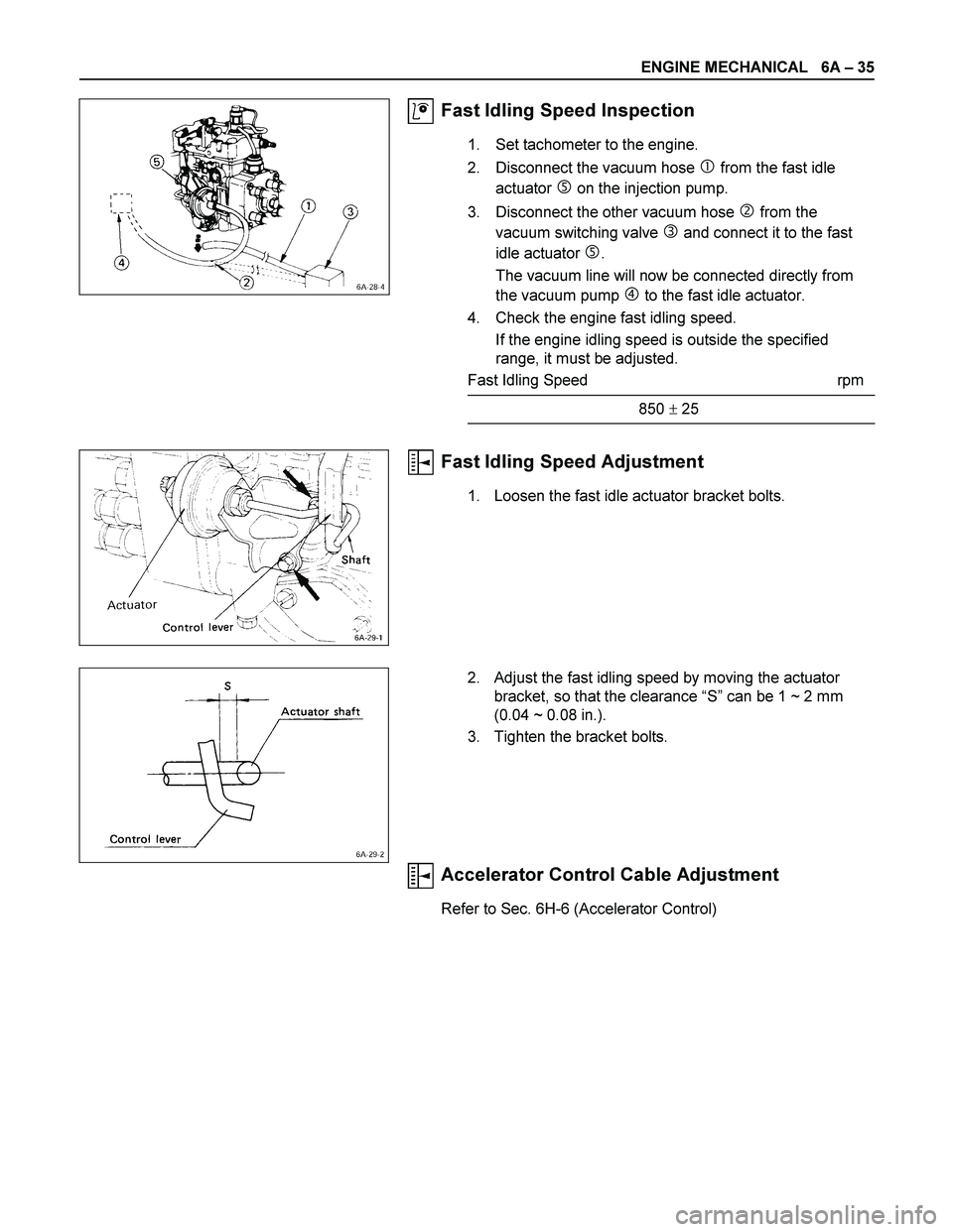
Fast Idling Speed Inspection
1. Set tachometer to the engine.
2. Disconnect the vacuum hose
� from the fast idle
actuator
� on the injection pump.
3. Disconnect the other vacuum hose
� from the
vacuum switching valve
� and connect it to the fast
idle actuator
�.
The vacuum line will now be connected directly from
the vacuum pump
� to the fast idle actuator.
4. Check the engine fast idling speed.
If the engine idling speed is outside the specified
range, it must be adjusted.
Fast Idling Speed rpm
850 � 25
Fast Idling Speed Adjustment
1. Loosen the fast idle actuator bracket bolts.
2. Adjust the fast idling speed by moving the actuator
bracket, so that the clearance “S” can be 1 ~ 2 mm
(0.04 ~ 0.08 in.).
3. Tighten the bracket bolts.
Accelerator Control Cable Adjustment
Refer to Sec. 6H-6 (Accelerator Control)
Page 1178 of 4264

Remove the spline yoke flange bolt at the transfer output
shaft.
Do not allow the spline yoke to fall away from the front")
6A – 38 ENGINE MECHANICAL
6. Front propeller shaft (for 4x4 model)
Remove the spline yoke flange bolt at the transfer output
shaft.
Do not allow the spline yoke to fall away from the front
propeller shaft.
If the spline yoke should fall away from the front propeller
shaft, align the setting marks on the spline yoke and the
propeller shaft to reassemble the two marks. The setting
marks are punched circles approx. 3mm (0.12 in) in
diameter.
7. Clutch slave cylinder (for M/T model)
8. ATF pipe (for A/T model)
9 Shift control cable (for A/T model)
10. Transmission sensor harness
Remove the vehicle speed sensor connector, inhibitor
switch connector (A/T), ATF temperature sensor
connector, back up light switch connector (M/T) from
transmission.
11. Breather hose (for A/T model)
12. Transmission shift lever (for M/T model)
Remove the shift lever from the floor.
13. Transfer shift lever (for 4x4 model)
Remove the shift lever from the floor.
14. Transmission member
1) Support the transmission with the transmission jack.
2) Remove the transmission member mounting bolts
fixing the transmission member to the chassis frame.
15. Torque converter bolt (for A/T model)
1) Remove the under cover under the torque converter
housing.
2) Rotate the flywheel by using tire lever or some other
tool, and then remove the torque converter bolts.
16. Transmission coupling bolt
1) Support the engine with the garage jack.
2) Use the jack to slightly lower the transmission.
3) Remove the transmission coupling bolts.
17. Transmission (and transfer)
Separate the transmission (and transfer) from the
engine.Take care not to damage the transmission, the
engine, and their related parts..
F06R300007 P1010025
Page 1179 of 4264
 Drain the engine coolant.
2) Remove the reservoir hose.
3) Remove the upper and lower hose.
4) Remove the fan guide.
5) Remove the radiat")
ENGINE MECHANICAL 6A – 39
18. Radiator
1) Drain the engine coolant.
2) Remove the reservoir hose.
3) Remove the upper and lower hose.
4) Remove the fan guide.
5) Remove the radiator.
19. Fan
P1010034
20. Air cleaner
1) Remove the MAF sensor connector (4JA1TC/4JH1TC) from air cleaner duct.
2) Remove the air cleaner duct and the air cleaner box from engine room.
3) Remove the two air ducts from inter cooler (4JA1TC/4JH1TC).
21. Power Steering Pump Loosen the power steering pump adjust plate bolt, then
remove the power steering pump assembly. Place the
power steering pump assembly along with piping on the
body side.
22. Air conditioner compressor 1) Remove air compressor magnet connector.
2) Remove the air conditioner compressor. Place the air conditioner compressor along with piping on the body
side.
23. Engine Control Cable Remove the engine control cable from its bracket
(4JA1TC/4JH1TC) or the injection pump (4JA1T(L)).
24. Vacuum Piping Remove the vacuum pipe from the vacuum pump, the
EGR valve, injection pump FICD (4JA1T(L)).
25. Engine Harness 1) Remove following connectors from engine.
� TPS connector
� Oil pressure switch connector
� Thermo switch connector
� Injection pump connector
� Engine earth
� Thermometer unit connector
� TDC sensor
2) Remove the clips fixing engine harness.
P1010009
Page 1183 of 4264
ENGINE MECHANICAL 6A – 43
ENGINE OVERHAUL
REMOVAL
EXTERNAL PARTS
RTW36AMF000401
Removal Steps
1. Clutch Assembly or Flex Plate
2. Intake Pipe and Throttle Body
3-1. EGR Pipe
3-2. EGR cooler (EURO III model only)
4. EGR Valve
5. Oil Level Gauge
6. Fuel Filter Assembly (Except EURO III)
7. Fuel Filter Bracket (Except EURO III)
8. Fuel Injection Pipe with Clip
9. Power Steering Oil Pump Bracket
10. Intake Manifold
11. Engine Mounting Bracket and Foot
12. Injection Pump Cover
13. Injection Pump
14. Starter Motor
15. Oil Pressure Warning Switch
16. Fuel Leak Off Pipe
17. Oil Cooler Water Pipe
18. Cooling Fan Pulley
19. Heat Protector
20. Catalytic Converter
21. Turbocharger
22. Compressor Bracket
23. Vacuum Pump Oil Return Hose
24. Generator and Adjusting Plate
25. Water Inlet Pipe
26. Generator Bracket
27. Oil Cooler with Oil Filter
28. Exhaust Manifold
Page 1186 of 4264
6A – 46 ENGINE MECHANICAL
13. Injection Pump
Rrefer to secton 6C-19 (Injection Iump)
14. Starter Motor
15. Oil Pressure Warning Switch
16. Fuel Leak Off Pipe
17. Oil Cooler Water Pipe
18. Cooling Fan Pulley
19. Heat Protector
20. Catalytic Converter
21. Turbocharger
1) Disconnect the water hose between thermostat
housing cover and turbocharger.
2) Disconnect the water hose between water inlet pipe
and turbocharger.
3) Remove the oil feed pipe.
4) Remove the oil return pipe.
5) Remove the turbocharger and the gasket.
NOTE:
Plug the turbocharger body oil ports and water ports after
removing the turbocharger assembly to prevent the entry
of foreign material.
22. Compressor Bracket
23. Vacuum Pump Oil Return Hose
24. Generator and Adjusting Plate
25. Water Inlet Pipe
26. Generator Bracket
27. Oil Cooler with Oil Filter
28. Exhaust Manifold
027R100007
037RY00001
Page 1187 of 4264
ENGINE MECHANICAL 6A – 47
1
DISASSEMBLY
INTERNAL PARTS
MAJOR COMPONENTS
Disassembly Steps-1
1.
Water bypass hose 5.
Rocker arm shaft and rocker
2.
Thermostat housing with thermo arm
switch 6. Push rod
3.
Cylinder head cover 7.
Cylinder head
4.
Injection nozzle and bracket 8.
Cylinder head gasket
011R300001


14. Starter Motor
15. Oil Pressure Warning Switch
16. Fuel Leak Off Pipe
17. Oil Cooler Wat")
