Page 1190 of 4264
6A – 50 ENGINE MECHANICAL
Disassembly
1. Water Bypass Hose
2. Thermostat Housing with Thermo Switch
3. Cylinder Head Cover
4. Injection Nozzle and Bracket
1. Remove the injection nozzle bracket bolts.
2. Use the injection nozzle remover and the sliding
hammer to remove the injection nozzle together.
Injection Nozzle Remover: 5-8840-2723-0
Sliding Hammer: 5-8840-0019-0
5. Rocker Arm Shaft and Rocker Arm
Loosen the rocker arm shaft bracket bolts in numerical
order a little at a time.
Note:
Failure to loosen the rocker arm shaft bracket bolts in
numerical order a little at a time will adversely affect the
rocker arm shaft.
6. Push Rod
7. Cylinder Head
Loosen the cylinder head bolts in numerical order a little at
a time.
Note:
Failure to loosen the cylinder head bolts in numerical
order a little at a time will adversely affect the cylinder
head lower surface.
8. Cylinder Head Gasket
9. Crankshaft Damper Pulley
011R100002
011RY00005
011RY00006
011RY00007
Page 1243 of 4264
ENGINE MECHANICAL 6A – 103
Reassembly Steps-3
27.
Cylinder head gasket 31. Thermostat housing with thermo
switch
28.
Cylinder head 32.
Water by-pass hose
29.
Push rod 33.
Injection nozzle and bracket
30. Rocker arm shaft and rocker
arm 34.
Cylinder head cover with gasket
011R300002
Page 1258 of 4264
6A – 118 ENGINE MECHANICAL
INSTALLATION
EXTERNAL PARTS
RTW36AMF000701
Installation Steps
1.
Exhaust Manifold 18. Engine Mounting Bracket and
2.
Oil Cooler with Oil Filter Foot
3. Generator Bracket 19. Intake Manifold
4. Water Inlet Pipe 20. Power Steering Oil Pump
5.
Generator and Adjusting Plate Bracket
6.
Vacuum Pump Oil Return Hose 21. Fuel Injection Pipe with Clip
7.
Compressor Bracket 22. Fuel Filter Bracket (Except
EURO III)
8. Turbocharger 23. Fuel Filter Assembly (Except
EURO III)
9. Catalytic Converter 24. Oil Level Gauge
10. Heat Protector 25. EGR Valve
11. Cooling Fan Pulley 26-1. EGR Pipe
12. Oil Cooler Water Pipe 26-2. EGR Cooler (EURO III model
only)
13. Fuel Leak Off Pipe 27. Intake Pipe and Throttle Body
(4JA1TC/4JH1TC only)
14. Oil Pressure Warning Switch 28. Clutch Assembly or Flex Plate
15. Starter Motor
16. Injection Pump
17. Injection Pump Cover
Page 1262 of 4264

6A – 122 ENGINE MECHANICAL
RTW46ASH001601
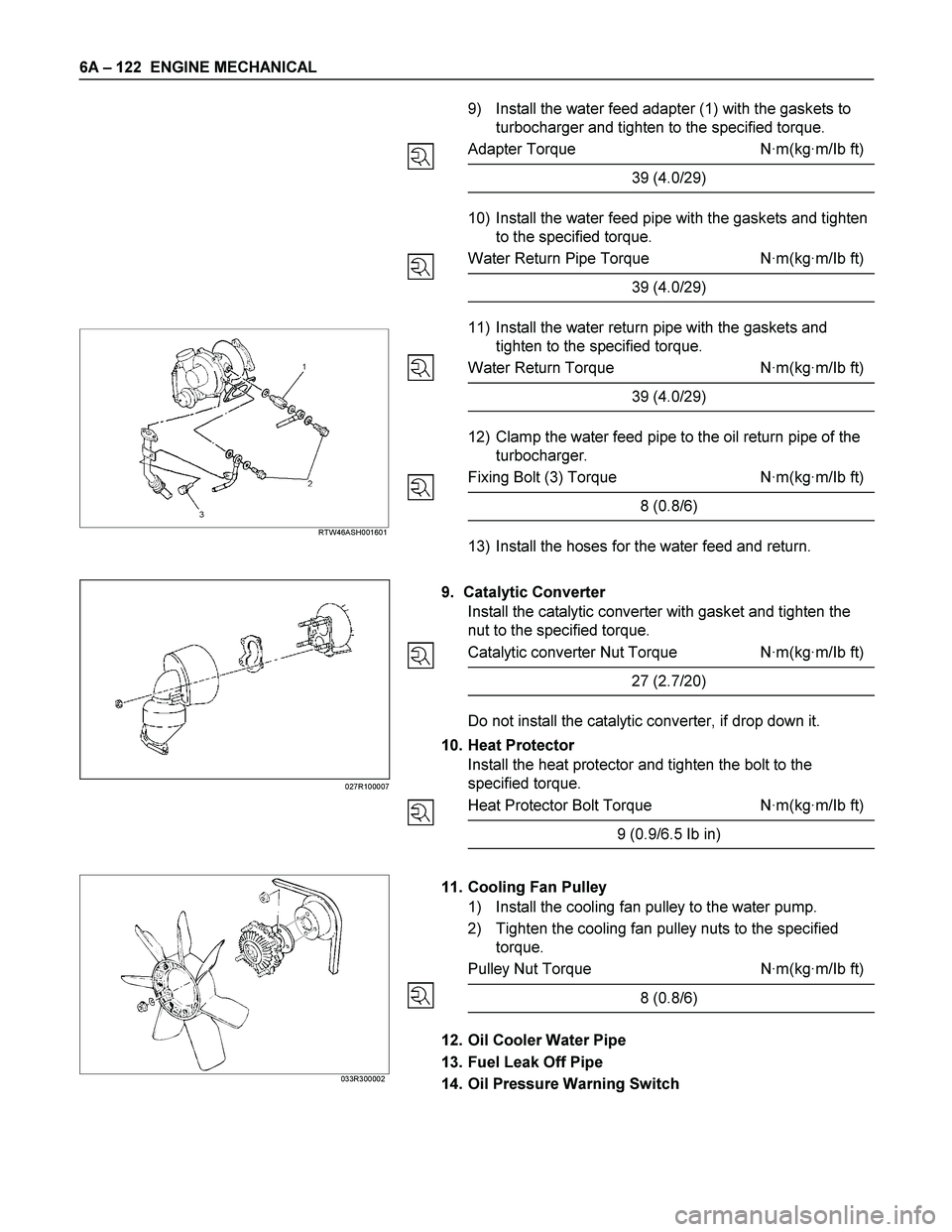
9) Install the water feed adapter (1) with the gaskets to
turbocharger and tighten to the specified torque.
Adapter Torque N·m(kg·m/Ib ft)
39 (4.0/29)
10) Install the water feed pipe with the gaskets and tighten
to the specified torque.
Water Return Pipe Torque N·m(kg·m/Ib ft)
39 (4.0/29)
11) Install the water return pipe with the gaskets and
tighten to the specified torque.
Water Return Torque N·m(kg·m/Ib ft)
39 (4.0/29)
12) Clamp the water feed pipe to the oil return pipe of the
turbocharger.
Fixing Bolt (3) Torque N·m(kg·m/Ib ft)
8 (0.8/6)
13) Install the hoses for the water feed and return.
9. Catalytic Converter
Install the catalytic converter with gasket and tighten the
nut to the specified torque.
Catalytic converter Nut Torque N·m(kg·m/Ib ft)
27 (2.7/20)
Do not install the catalytic converter, if drop down it.
10. Heat Protector
Install the heat protector and tighten the bolt to the
specified torque.
Heat Protector Bolt Torque N·m(kg·m/Ib ft)
9 (0.9/6.5 Ib in)
033R300002
11. Cooling Fan Pulley
1) Install the cooling fan pulley to the water pump.
2) Tighten the cooling fan pulley nuts to the specified
torque.
Pulley Nut Torque N·m(kg·m/Ib ft)
8 (0.8/6)
12. Oil Cooler Water Pipe
13. Fuel Leak Off Pipe
14. Oil Pressure Warning Switch
027R100007
Page 1266 of 4264
6A – 126 ENGINE MECHANICAL
LUBRICATION SYSTEM
LUBRICATING OIL FLOW
1. Oil Pump Relief Valve Operating Pressure: 6.2 - 7.8kg/cm 2 (608 - 764Kpa)
2. Regulating Valve Operating Pressure: 5.7 - 6.3kg/cm 2 (558.6 - 617.4Kpa)
3. Oil Cooler Relief Valve Opening Pressure: 2.8 - 3.4kg/cm 2 (270 - 330Kpa)
4. Oil Filter Relief Valve Opening Pressure: 0.8 - 1.2kg/cm 2 (78.4 - 117.6Kpa)
5. Oil Pressure Switch Operating Pressure: 0.3 - 0.5kg/cm 2 (29.4 - 49.0Kpa)
6. Regulating Valve: 1.8 - 2.2kg/cm 2 (176 - 216Kpa)
The 4J series engine has a full flow type lubricating system.
Lubricating oil is pumped from the oil pump to the cylinder body oil gallery through the oil cooler and the oil filter. It is
then delivered to the vital parts of the engine from the cylinder body oil gallery.
Oiling jets installed on the cylinder body spray engine oil to the piston backside faces to achieve maximum piston
cooling effect.
Page 1352 of 4264

6D – 14 ENGINE ELECTRICAL
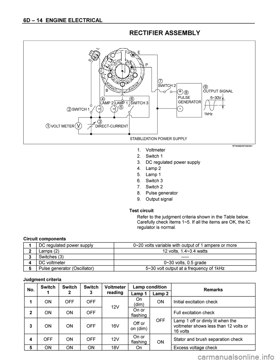
RECTIFIER ASSEMBLY
RTW46DSF000301
1. Voltmeter
2. Switch 1
3. DC regulated power supply
4. Lamp 2
5. Lamp 1
6. Switch 3
7. Switch 2
8. Pulse generator
9. Output signal
Test circuit
Refer to the judgment criteria shown in the Table below.
Carefully check Items 1~5. If all the items are OK, the IC
regulator is normal.
Circuit components
1 DC regulated power supply 0~20 volts variable with output of 1 ampere or more
2 Lamps (2) 12 volts, 1.4~3.4 watts
3 Switches (3) -----
4 DC voltmeter 0~30 volts, 0.5 grade
5 Pulse generator (Oscillator) 5~30 volt output at a frequency of 1kHz
Judgment criteria
Lamp condition
No. Switch
1 Switch
2 Switch
3 Voltmeter
reading
Lamp 1 Lamp 2Remarks
1 ON OFF OFF On
(dim) ON Initial excitation check
2 ON ON OFF 12V
On or
flashingFull excitation check
3 ON ON OFF 16V Off or
on (dim)OFF
Lamp 1 off or dimly lit when the
voltmeter shows less than 12 volts or
16 volts
4 OFF ON OFF 12V On or
flashingStator and brush separation check
5 ON ON ON 18V On ON
Excess voltage check
Page 1360 of 4264

6D – 22 ENGINE ELECTRICAL
STARTER MOTOR
REMOVAL AND INSTALLATION
Read this Section carefully before performing any removal and installation procedure. This Section gives you
important points as well as the order of operation. Be sure that you understand everything in this Section before you
begin.
Important Operations - Removal
Starter Motor
1. Disconnect the battery cable and the ground cable at the battery terminals.
2. Disconnect the magnetic switch cable at the terminal bolts.
3. Disconnect the battery cable at the starter motor and the ground cable at the cylinder body.
4. Remove the starter motor from the engine.
Important Operations – Installation
Follow the removal procedure in the reverse order to
perform the installation procedure. Pay careful attention to
the important points during the installation procedure.
Starter Motor
1. Install the starter motor to the rear plate.
2. Tighten the starter motor bolts to the specified torque.
Starter Motor Bolt Torque N �m (kg �m/lb �ft)
85 (8.7/63)
3. Reconnect the battery cable at the starter motor and
the ground cable at the cylinder body.
4. Reconnect the battery cable and the ground cable at the battery terminals.
Page 1361 of 4264
ENGINE ELECTRICAL 6D – 23
DISASSEMBLY
RTW460LF000201
Disassembly Step
1.
Lead wire
14. Armature
2.
Bolt 15. Bolt
3.
Magnetic switch assembly 16. Bearing retainer
4.
Torsion spring 17. Pinion assembly
5.
Plunger 18. Pinion stopper clip
6.
Dust cover 19. Pinion stopper
7.
Magnetic switch 20. Return spring
8.
Screw 21. Pinion shaft
9.
Through bolt 22. Clutch
10.
Rear cover 23. Dust cover
11.
Motor assembly 24. Shift lever
12.
Brush holder 25. Gear case
13.
Yoke