Page 1108 of 4264
8B-10 CRUISE CONTROL SYSTEM
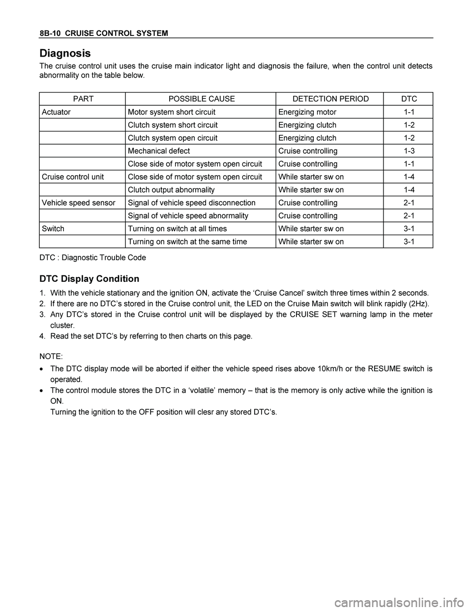
Diagnosis
The cruise control unit uses the cruise main indicator light and diagnosis the failure, when the control unit detects
abnormality on the table below.
PART POSSIBLE CAUSE DETECTION PERIOD DTC
Actuator Motor system short circuit Energizing motor 1-1
Clutch system short circuit Energizing clutch 1-2
Clutch system open circuit Energizing clutch 1-2
Mechanical defect Cruise controlling 1-3
Close side of motor system open circuit Cruise controlling 1-1
Cruise control unit Close side of motor system open circuit While starter sw on 1-4
Clutch output abnormality While starter sw on 1-4
Vehicle speed sensor Signal of vehicle speed disconnection Cruise controlling 2-1
Signal of vehicle speed abnormality Cruise controlling 2-1
Switch Turning on switch at all times While starter sw on 3-1
Turning on switch at the same time While starter sw on 3-1
DTC : Diagnostic Trouble Code
DTC Display Condition
1. With the vehicle stationary and the ignition ON, activate the ‘Cruise Cancel’ switch three times within 2 seconds.
2. If there are no DTC’s stored in the Cruise control unit, the LED on the Cruise Main switch will blink rapidly (2Hz).
3. Any DTC’s stored in the Cruise control unit will be displayed by the CRUISE SET warning lamp in the meter
cluster.
4. Read the set DTC’s by referring to then charts on this page.
NOTE:
� The DTC display mode will be aborted if either the vehicle speed rises above 10km/h or the RESUME switch is
operated.
� The control module stores the DTC in a ‘volatile’ memory – that is the memory is only active while the ignition is
ON.
Turning the ignition to the OFF position will clesr any stored DTC’s.
Page 1111 of 4264
CRUISE CONTROL SYSTEM 8B-13
DTC 1–1 Motor System Short Circuit
Step Action Value(s) YES NO
1 1. Turn the starter switch off.
2. Disconnect the actuator connector C-119.
3. Measure resistance between actuator side
connector terminal 1 and 2.
If control plate position is fully opened or fully
closed, resistance can not be measure.
Is there resistance within range specified in the
value(s) column?
More than
4.2�
Go to Step 2
Replace the
actuator
2 Measure continuity between harness side connector
C-119 terminal 1 and the ground, terminal 2 and the
ground, and terminals 1 and 2.
Are the results same as specified in the value(s)
column?
No
continuity
Replace the
control unit
Repair or
replace the
harness
Page 1112 of 4264
8B-14 CRUISE CONTROL SYSTEM
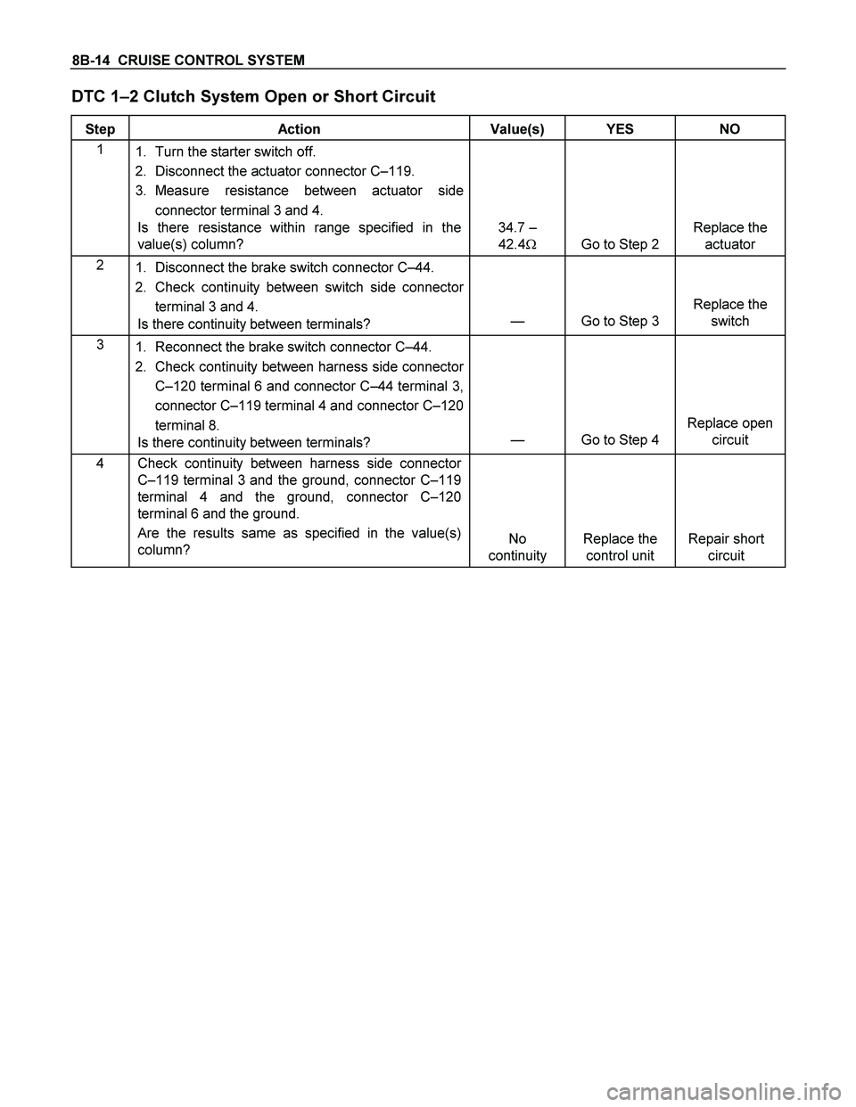
DTC 1–2 Clutch System Open or Short Circuit
Step Action Value(s) YES NO
1
1. Turn the starter switch off.
2. Disconnect the actuator connector C–119.
3. Measure resistance between actuator side
connector terminal 3 and 4.
Is there resistance within range specified in the
value(s) column?
34.7 –
42.4�
Go to Step 2
Replace the
actuator
2
1. Disconnect the brake switch connector C–44.
2. Check continuity between switch side connector
terminal 3 and 4.
Is there continuity between terminals?
—
Go to Step 3
Replace the
switch
3
1. Reconnect the brake switch connector C–44.
2. Check continuity between harness side connector
C–120 terminal 6 and connector C–44 terminal 3,
connector C–119 terminal 4 and connector C–120
terminal 8.
Is there continuity between terminals?
—
Go to Step 4
Replace open
circuit
4 Check continuity between harness side connector
C–119 terminal 3 and the ground, connector C–119
terminal 4 and the ground, connector C–120
terminal 6 and the ground.
Are the results same as specified in the value(s)
column?
No
continuity
Replace the
control unit
Repair short
circuit
Page 1113 of 4264
CRUISE CONTROL SYSTEM 8B-15
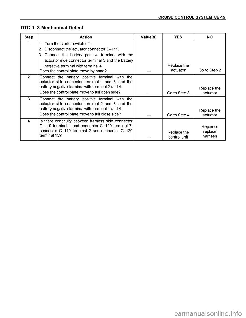
DTC 1–3 Mechanical Defect
Step Action Value(s) YES NO
1
1. Turn the starter switch off.
2. Disconnect the actuator connector C–119.
3. Connect the battery positive terminal with the
actuator side connector terminal 3 and the battery
negative terminal with terminal 4.
Does the control plate move by hand?
—
Replace the
actuator
Go to Step 2
2 Connect the battery positive terminal with the
actuator side connector terminal 1 and 3, and the
battery negative terminal with terminal 2 and 4.
Does the control plate move to full open side?
—
Go to Step 3
Replace the
actuator
3 Connect the battery positive terminal with the
actuator side connector terminal 2 and 3, and the
battery negative terminal with terminal 1 and 4.
Does the control plate move to full close side?
—
Go to Step 4
Replace the
actuator
4 Is there continuity between harness side connector
C–119 terminal 1 and connector C–120 terminal 7,
connector C–119 terminal 2 and connector C–120
terminal 15?
—
Replace the
control unit
Repair or
replace
harness
Page 1114 of 4264
8B-16 CRUISE CONTROL SYSTEM
DTC 1–4 Close Side of Motor System Open Circuit
Step Action Value(s) YES NO
1
1. Turn the starter switch off.
2. Disconnect the actuator connector C–119.
3. Measure resistance between actuator side
connector terminal 1 and 2.
If control plate position is fully opened or fully
closed, resistance can not be measured.
Is there resistance within range specified in the
value(s) column?
More than
4.2�
Go to Step 2
Replace the
actuator
2 Is there continuity between harness side connector
C–119 terminal 1 and connector C–120 terminal 7,
harness side connector C–119 terminal 2 and
connector C–120 terminal 15?
—
Replace the
control unit
Repair or
replace the
harness
Page 1116 of 4264
8B-18 CRUISE CONTROL SYSTEM
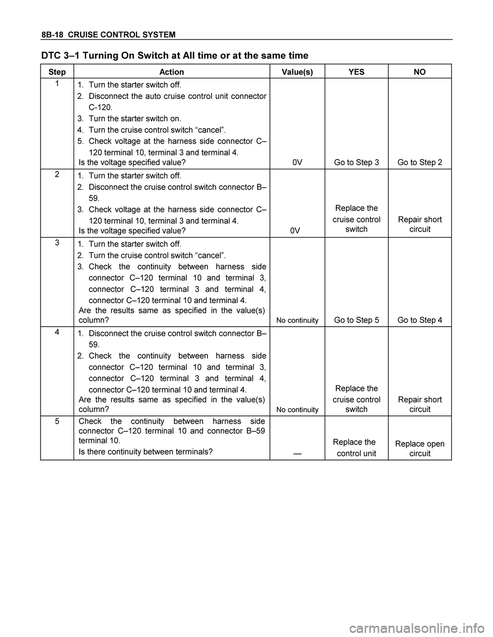
DTC 3–1 Turning On Switch at All time or at the same time
Step Action Value(s) YES NO
1
1. Turn the starter switch off.
2. Disconnect the auto cruise control unit connector
C-120.
3. Turn the starter switch on.
4. Turn the cruise control switch “cancel”.
5. Check voltage at the harness side connector C–
120 terminal 10, terminal 3 and terminal 4.
Is the voltage specified value?
0V
Go to Step 3
Go to Step 2
2
1. Turn the starter switch off.
2. Disconnect the cruise control switch connector B–
59.
3. Check voltage at the harness side connector C–
120 terminal 10, terminal 3 and terminal 4.
Is the voltage specified value?
0V
Replace the
cruise control
switch
Repair short
circuit
3
1. Turn the starter switch off.
2. Turn the cruise control switch “cancel”.
3. Check the continuity between harness side
connector C–120 terminal 10 and terminal 3,
connector C–120 terminal 3 and terminal 4,
connector C–120 terminal 10 and terminal 4.
Are the results same as specified in the value(s)
column?
No continuity
Go to Step 5
Go to Step 4
4
1. Disconnect the cruise control switch connector B–
59.
2. Check the continuity between harness side
connector C–120 terminal 10 and terminal 3,
connector C–120 terminal 3 and terminal 4,
connector C–120 terminal 10 and terminal 4.
Are the results same as specified in the value(s)
column?
No continuity
Replace the
cruise control
switch
Repair short
circuit
5 Check the continuity between harness side
connector C–120 terminal 10 and connector B–59
terminal 10.
Is there continuity between terminals?
—
Replace the
control unit
Replace open
circuit
Page 1121 of 4264
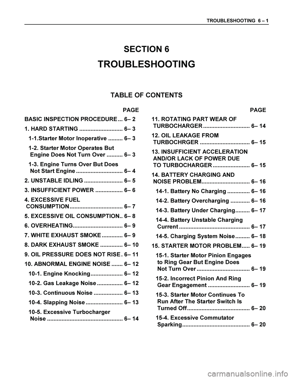
TROUBLESHOOTING 6 – 1
SECTION 6
TROUBLESHOOTING
TABLE OF CONTENTS
PAGE PAGE
BASIC INSPECTION PROCEDURE ... 6– 2
1. HARD STARTING ........................... 6– 3
1-1.Starter Motor Inoperative ......... 6– 3
1-2. Starter Motor Operates But
Engine Does Not Turn Over .......... 6– 3
1-3. Engine Turns Over But Does
Not Start Engine ............................. 6– 4
2. UNSTABLE IDLING ........................ 6– 5
3. INSUFFICIENT POWER ................. 6– 6
4. EXCESSIVE FUEL
CONSUMPTION ................................. 6– 7
5. EXCESSIVE OIL CONSUMPTION.. 6– 8
6. OVERHEATING............................... 6– 9
7. WHITE EXHAUST SMOKE ............. 6– 9
8. DARK EXHAUST SMOKE .............. 6– 10
9. OIL PRESSURE DOES NOT RISE . 6– 11
10. ABNORMAL ENGINE NOISE ....... 6– 12
10-1. Engine Knocking.................... 6– 12
10-2. Gas Leakage Noise ................ 6– 12
10-3. Continuous Noise .................. 6– 13
10-4. Slapping Noise ....................... 6– 13
10-5. Excessive Turbocharger
Noise ............................................... 6– 14
11. ROTATING PART WEAR OF
TURBOCHARGER ............................. 6– 14
12. OIL LEAKAGE FROM
TURBOCHRGER ............................... 6– 15
13. INSUFFICIENT ACCELERATION
AND/OR LACK OF POWER DUE
TO TURBOCHARGER ....................... 6– 15
14. BATTERY CHARGING AND
NOISE PROBLEM.............................. 6– 16
14-1. Battery No Charging .............. 6– 16
14-2. Battery Overcharging ............ 6– 16
14-3. Battery Under Charging......... 6– 17
14-4. Battery Unstable Charging
Current ............................................ 6– 17
14-5. Charging System Noise ......... 6– 18
15. STARTER MOTOR PROBLEM..... 6– 19
15-1. Starter Motor Pinion Engages
to Ring Gear But Engine Does
Not Turn Over ................................. 6– 19
15-2. Incorrect Pinion And Ring
Gear Engagement .......................... 6– 19
15-3. Starter Motor Continues To
Run After The Starter Switch Is
Turned Off ....................................... 6– 20
15-4. Excessive Commutator
Sparking .......................................... 6– 20
Page 1123 of 4264
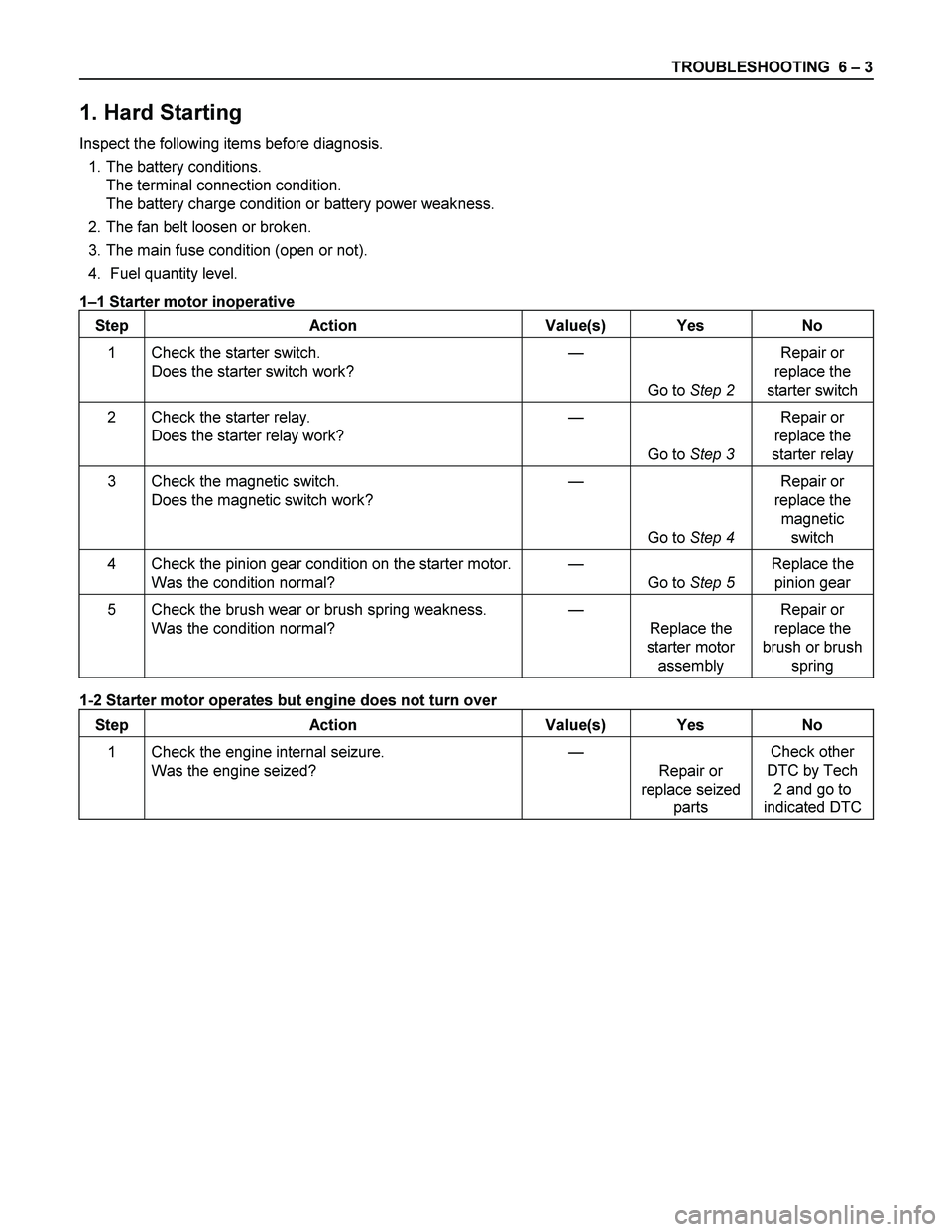
TROUBLESHOOTING 6 – 3
1. Hard Starting
Inspect the following items before diagnosis.
1. The battery conditions.
The terminal connection condition.
The battery charge condition or battery power weakness.
2. The fan belt loosen or broken.
3. The main fuse condition (open or not).
4. Fuel quantity level.
1–1 Starter motor inoperative
Step Action Value(s) Yes No
1 Check the starter switch.
Does the starter switch work? —
Go to Step 2 Repair or
replace the
starter switch
2 Check the starter relay.
Does the starter relay work? —
Go to Step 3 Repair or
replace the
starter relay
3 Check the magnetic switch.
Does the magnetic switch work? —
Go to Step 4 Repair or
replace the
magnetic
switch
4 Check the pinion gear condition on the starter motor.
Was the condition normal? —
Go to Step 5 Replace the
pinion gear
5 Check the brush wear or brush spring weakness.
Was the condition normal? —
Replace the
starter motor
assembly Repair or
replace the
brush or brush
spring
1-2 Starter motor operates but engine does not turn over
Step Action Value(s) Yes No
1 Check the engine internal seizure.
Was the engine seized? —
Repair or
replace seized
parts Check other
DTC by Tech
2 and go to
indicated DTC