Page 1003 of 4264
ELECTRICAL-BODY AND CHASSIS 8A-345
REMOVAL AND INSTALLATION
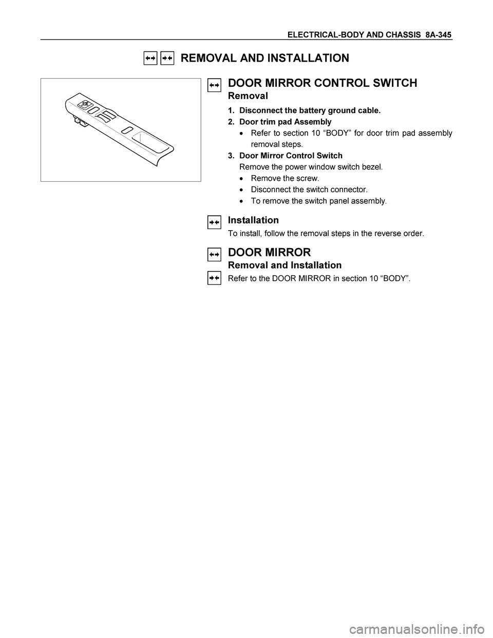
DOOR MIRROR CONTROL SWITCH
Removal
1. Disconnect the battery ground cable.
2. Door trim pad Assembly
� Refer to section 10 “BODY” for door trim pad assembly
removal steps.
3. Door Mirror Control Switch
Remove the power window switch bezel.
� Remove the screw.
� Disconnect the switch connector.
� To remove the switch panel assembly.
Installation
To install, follow the removal steps in the reverse order.
DOOR MIRROR
Removal and Installation
Refer to the DOOR MIRROR in section 10 “BODY”.
Page 1004 of 4264
8A-346 ELECTRICAL-BODY AND CHASSIS
INSPECTION AND REPAIR
Switch side
D-19
Door Mirror Control Switch
1. Switch side Connector Circuit
Check continuity between the switch connector terminals
while operating the door mirror control switch as shown in
the following table.
RTW48AMF000601
MV, MH, b, and e terminals have internal connections (circuitry).
4-point switch (Will not operate at intermediate positions.)
Harness side
D-19
2. Harness Side Connector Circuit
Remove the connector No.
D-19 of the mirror control
switch and check voltage and continuity of the harness side
connector.
� When there is no continuity at the terminal No. 2, 3, 9
and 10, it is considered that the circuit with terminal No.
7 (W/B) is defective.
Page 1005 of 4264
ELECTRICAL-BODY AND CHASSIS 8A-347
� When there is no continuity at either one of the circuit
No, 5, 7, 8, or 10, the motor in the mirror of the circuit or
the circuit itself is defective.
Terminal
No. Wire
color Connection to Check item Connecting
terminal Check condition Standard
7 W/B LH mirror & RH
mirror Continuity 7-Ground - No continuity
4 R/Y Fuse C-11 (10A) Voltage 4-Ground Starter SW “ACC”
position Approx.
12V
10 W/R RH mirror-LH/RH 10-7 -
2 B/W RH mirror-Up/Down 2-7 -
3 B/R LH mirror-Up/Down Continuity 3-7 - Continuity
8 B Ground 8-Ground -
9 W/G LH mirror-LH/RH 9-7 -
Harness side
D-19
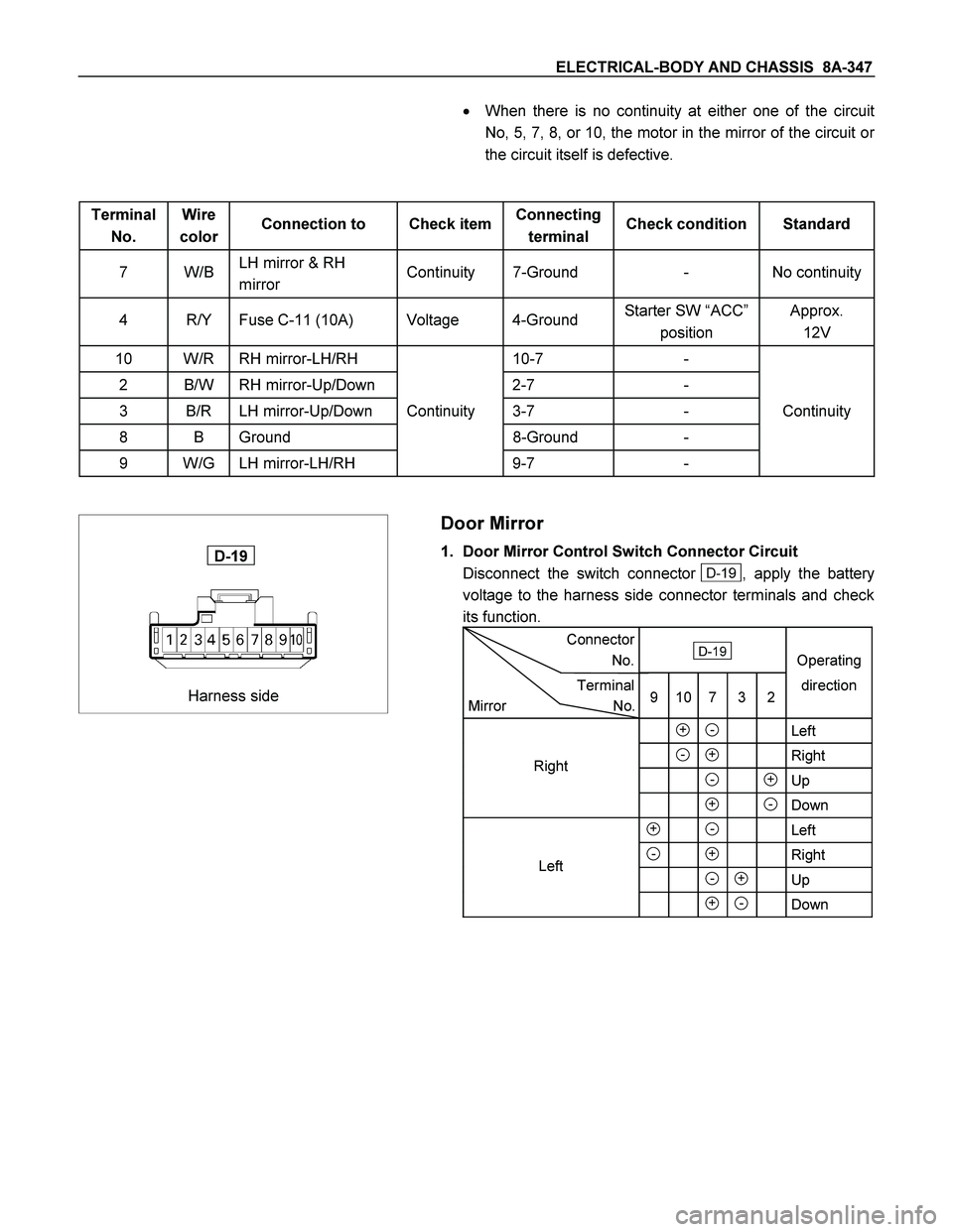
Door Mirror
1. Door Mirror Control Switch Connector Circuit
Disconnect the switch connector
D-19 , apply the battery
voltage to the harness side connector terminals and check
its function.
Connector
No. D-19
Operating
Terminal
Mirror No.9 10 7 3 2direction
+ - Left
- + Right
- +Up
+ -Down
+ - Left
- + Right
- + Up
+ - Down
Left Right
Page 1011 of 4264
 and 9
B-56
Poor f")
ELECTRICAL-BODY AND CHASSIS 8A-353
TROUBLE SHOOTING
Rear defogger inoperative
Checkpoint Trouble Cause Countermeasure
Reinstall or replace the fuse
No. C-7 (15A) and 9
B-56
Poor fuse contact or blown
NG
Reinstall or replace the fuse
SBF-10 (20A)
SBF-10 (20A, Fuse box)
Poor fuse contact or blown
Replace the rear defogger
switch
Rear defogger switch function
Switch malfunction
NG NG OK
OK OK
Fuse No. C-7 (15A, Fuse box)
and 9
B-56
Replace the rear defogger
relay
Relay malfunction
NG
Continued on the next page
Rear defogger relay function
Repair grounding point
D-2
contact
Grounding point
C-2
Poor grounding point contact
NG OK
Repair open circuit or poor
connector contact between
fuse No. C-7 (15A) and 3
B-7, SBF-10 (20A) and 1
B-7, 2 B-7 (3 B-55) and
1
L-4, 4 B-7 (3 B-54)
and 3
B-46 or 1 B-46 and
C-2
Voltage between 1 L-4-
ground when the starter switch
and the rear defogger switch
are at on position (should be
battery voltage present)
Open circuit or poor connector
contact
NG OK
Page 1013 of 4264
ELECTRICAL-BODY AND CHASSIS 8A-355
REMOVAL AND INSTALLATION
865R300008
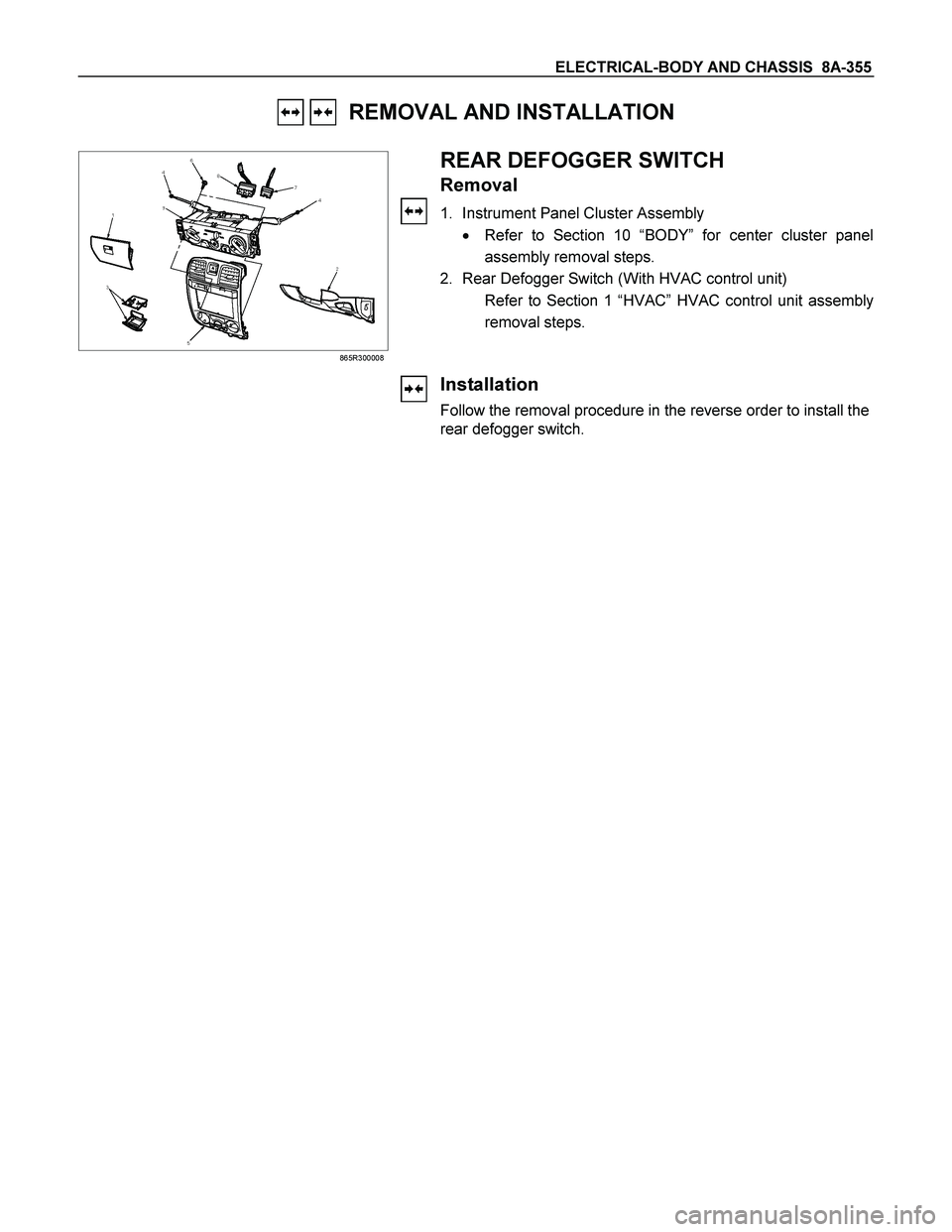
REAR DEFOGGER SWITCH
Removal
1. Instrument Panel Cluster Assembly
� Refer to Section 10 “BODY” for center cluster panel
assembly removal steps.
2. Rear Defogger Switch (With HVAC control unit)
Refer to Section 1 “HVAC” HVAC control unit assembly
removal steps.
Installation
Follow the removal procedure in the reverse order to install the
rear defogger switch.
Page 1014 of 4264
8A-356 ELECTRICAL-BODY AND CHASSIS
INSPECTION AND REPAIR
Switch side
B-57
REAR DEFOGGER SWITCH
Rear Defogger Switch Connections
Terminal No.
SW position 9 7 8
ON
OFF
B-7
REAR DEFOGGER RELAY
Check continuity between the relay terminals.
2- 1......................... No continuity
(When battery voltage is applied between
4 and 3)
2- 1......................... Continuity
INSPECTION OF REAR DEFOGGER HEAT
WIRE
� Heat wires are printed on the inner side of glass.
To clean, use a soft cloth and wipe horizontally along the
wires.
� Never use glass cleaner or equivalent.
� When measuring voltage, wind a piece of tin foil around the
tip of the negative probe and press the foil against the wire
with your finger as shown.
(1) Turn the ignition switch on.
(2) Turn the defogger switch on.
(3) Measure the voltage between the three points on the hea
t
wire and the (-) terminal with a voltmeter.
(4) Check that the voltage becomes smaller from
A to B to C.
Page 1030 of 4264
8A-372 ELECTRICAL-BODY AND CHASSIS
2WD-4WD Switch
REMOVAL AND INSTALLATION
825R300018
Removal
1. Remove the center cluster ASM
2. Disconnect the connector.
3. Remove the 2WD-4WD switch.
Installation
To install, follow the removal steps in the reverse order.
Page 1068 of 4264
8A-410 ELECTRICAL-BODY AND CHASSIS
ANTI THEFT INDICATOR
Removal
1. Disconnect the battery ground cable.
RTW3A0SH001301
2. Remove the side ventilation grille.
RTW08ASH000101
3. Disconnect the indicator connector and screw from the
backside of the side ventilation grille to remove the anti thef
t
indicator.
Installation
To install, follow the removal steps in the reverse order, noting
the following point.
1. Push in the switch with your fingers until it locks securely.