Page 981 of 4264

ELECTRICAL-BODY AND CHASSIS 8A-323
INSPECTION AND REPAIR
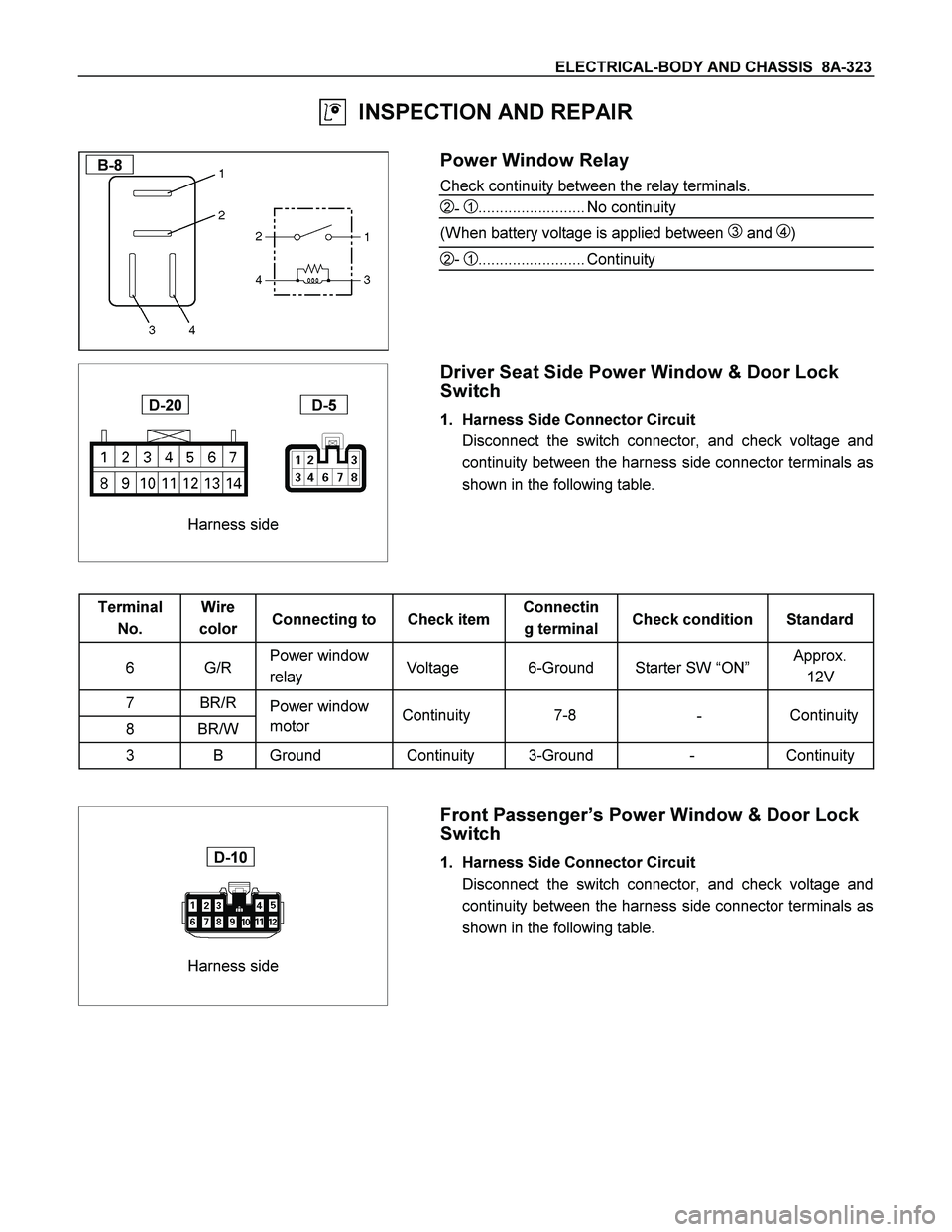
B-8
Power Window Relay
Check continuity between the relay terminals.
2- 1......................... No continuity
(When battery voltage is applied between
3 and 4)
2- 1......................... Continuity
Harness side
D-20 D-5
Driver Seat Side Power Window & Door Lock
Switch
1. Harness Side Connector Circuit
Disconnect the switch connector, and check voltage and
continuity between the harness side connector terminals as
shown in the following table.
Terminal
No. Wire
color Connecting to Check item Connectin
g terminal Check condition Standard
6 G/R Power window
relay Voltage 6-Ground Starter SW “ON” Approx.
12V
7 BR/R
Power window
8 BR/W motor
3 B Ground Continuity 3-Ground - Continuity
Harness side
D-10
Front Passenger’s Power Window & Door Lock
Switch
1. Harness Side Connector Circuit
Disconnect the switch connector, and check voltage and
continuity between the harness side connector terminals as
shown in the following table.
Continuity
- 7-8 Continuity
Page 982 of 4264

8A-324 ELECTRICAL-BODY AND CHASSIS
Terminal
No. Wire
color Connecting to Check item Connectin
g terminal Check condition Standard
11 G/R Power window
relay Voltage 11-Ground Starter SW “ON” Approx.
12V
12 BR/R
Power window
10 BR/W motor
5 B Ground Continuity 5-Ground - Continuity
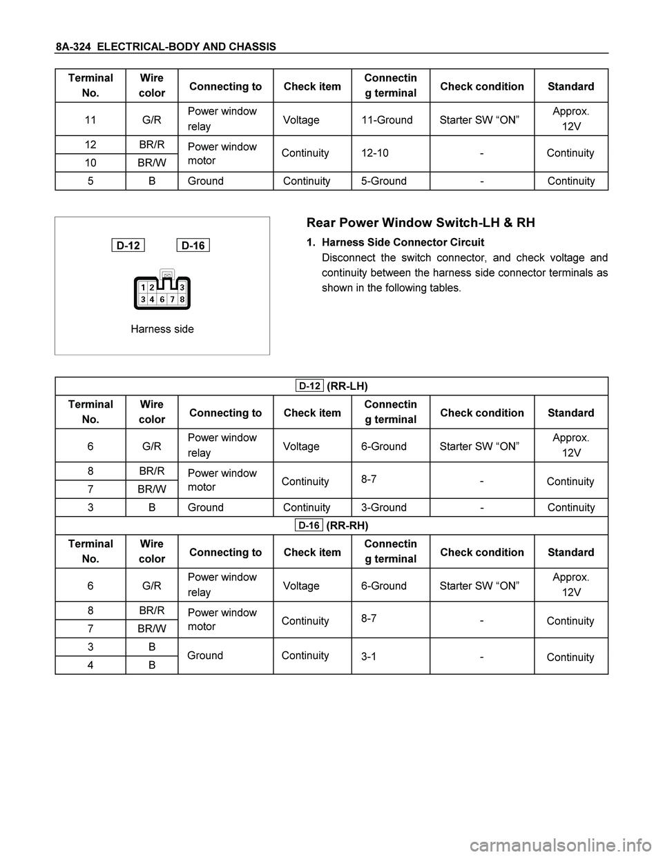
Harness side
D-12 D-16
Rear Power Window Switch-LH & RH
1. Harness Side Connector Circuit
Disconnect the switch connector, and check voltage and
continuity between the harness side connector terminals as
shown in the following tables.
D-12 (RR-LH)
Terminal
No. Wire
color Connecting to Check item Connectin
g terminal Check condition Standard
6 G/R Power window
relay Voltage 6-Ground Starter SW “ON” Approx.
12V
8 BR/R
Power window
7 BR/W motor
3 B Ground Continuity 3-Ground - Continuity
D-16 (RR-RH)
Terminal
No. Wire
color Connecting to Check item Connectin
g terminal Check condition Standard
6 G/R Power window
relay Voltage 6-Ground Starter SW “ON” Approx.
12V
8 BR/R
Power window
7 BR/W motor
3 B
4 B
Continuity - 12-10 Continuity
Continuity Continuity 8-7
-
Continuity Continuity 8-7
-
Ground Continuity
3-1
Continuity -
Page 983 of 4264
ELECTRICAL-BODY AND CHASSIS 8A-325
Harness side
D-5
Driver Seat Side Power Window Motor
1. Driver Seat Side Power Window & Door Lock Switch
Connector Circuit
Disconnect the switch connector, apply the battery voltage
(12V) to the harness side connector terminals and check
operation.
Connecting terminals
Operation
7 (BR/R) 8 (BR/W) direction
- + DOWN
+ - UP
2. Driver Seat Side Power Window Motor Connector
Circuit
Disconnect the switch connector, apply the battery voltage
(12V) to the motor side connector terminals and check
operation.
Connecting terminals
Operation
1 2 direction
+ - DOWN
- + UP
Page 984 of 4264
8A-326 ELECTRICAL-BODY AND CHASSIS
Harness side
D-10
Front Passenger’s Power Window Motor
1. Front Passenger’s Power Window Switch & Door Lock
Switch Connector Circuit
Disconnect the motor connector, apply the battery voltage
(12V) to the harness side connector terminals and check
operation.
Connecting terminals
Operation
12 (BR/R) 10 (BR/W) direction
- + DOWN
+ - UP
2. Front Passenger’s Power Window Motor Connector
Circuit
Disconnect the switch connector, apply the battery voltage
(12V) to the motor side connector terminals and check
operation.
Connecting terminals
Operation
1 2 direction
+ - DOWN
- + UP
Page 985 of 4264
ELECTRICAL-BODY AND CHASSIS 8A-327
Harness side
D-12
Rear Passenger’s Power Window Motor-LH
1. Rear Power Window Switch-LH Connector Circuit
Disconnect the motor connector, apply the battery voltage
(12V) to the harness side connector terminals and check
operation.
Connecting terminals
Operation
8 (BR/R) 7 (BR/W) direction
- + DOWN
+ - UP
2. Rear Power Window Motor-LH Connector Circuit
Disconnect the switch connector, apply the battery voltage
(12V) to the motor side connector terminals and check
operation.
Connecting terminals
Operation
1 2 direction
+ - DOWN
- + UP
Page 986 of 4264
8A-328 ELECTRICAL-BODY AND CHASSIS
Harness side
D-16
Rear Power Window Motor-RH
1. Rear Power Window Switch-RH Connector Circuit
Disconnect the motor connector, apply the battery voltage
(12V) to the harness side connector terminals and check
operation.
Connecting terminals
Operation
8 (BR/R) 7 (BR/W) direction
- + DOWN
+ - UP
2. Rear Power Window Motor-RH Connector Circuit
Disconnect the switch connector, apply the battery voltage
(12V) to the motor side connector terminals and check
operation.
Connecting terminals
Operation
1 2 direction
+ - DOWN
- + UP
Page 999 of 4264
ELECTRICAL-BODY AND CHASSIS 8A-341
TROUBLESHOOTING
QUICK CHART FOR CHECK POINT
Check Point Fuse
Door Mirror Door Mirror
Trouble Mode C-11
(10A) Control
Switch LH RH
1. Mirrors on the both sides do not operate
2. Mirror on the left (or right) side does not
operate
3. Mirrors on the both sides operate only in
the vertical
(or horizontal) direction
4. Mirror on the left side operates only in
the vertical
(or horizontal)direction
5. Mirror on the right side operates only in
the vertical
(or horizontal) direction
Cable
Harness
Page 1000 of 4264

8A-342 ELECTRICAL-BODY AND CHASSIS
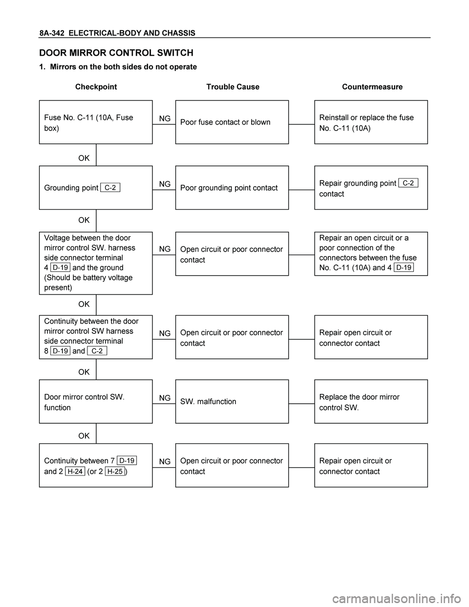
DOOR MIRROR CONTROL SWITCH
1. Mirrors on the both sides do not operate
Checkpoint Trouble Cause Countermeasure
Reinstall or replace the fuse
No. C-11 (10A)
Poor fuse contact or blown
NG
Repair grounding point
C-2
contact
Grounding point
C-2
Poor grounding point contact
Repair an open circuit or a
poor connection of the
connectors between the fuse
No. C-11 (10A) and 4
D-19
Voltage between the door
mirror control SW. harness
side connector terminal
4
D-19 and the ground
(Should be battery voltage
present)
Open circuit or poor connector
contact
NG NG OK
OK OK
Fuse No. C-11 (10A, Fuse
box)
Repair open circuit or
connector contact
Open circuit or poor connector
contact
NG Continuity between the door
mirror control SW harness
side connector terminal
8
D-19 and C-2
Replace the door mirror
control SW.
Door mirror control SW.
function
SW. malfunction
NG OK
Repair open circuit or
connector contact
Continuity between 7
D-19
and 2
H-24 (or 2 H-25 )
Open circuit or poor connector
contact
NG OK