Page 3210 of 4264
7B1-46 MANUAL TRANSMISSION
266RS049
7. Install the synchronizer assembly (20) to the
mainshaft (26).
The clutch hub face with the heavy boss must be
facing the 2nd gear side.
226RS048
8. Install clutch hub snap ring(19) by performing the
following steps:
� Select the snap ring which will provide the
minimum clearance between the 1st-2nd clutch
hub and the snap ring.
226RS050
�
There are three snap ring sizes available.
� The snap rings are color coded to indicate their
thickness as shown in the figure.
226RS021
Clutch Hub and Snap Ring Clearance
Standard: 0 - 0.1 mm (0 - 0.004 in)
Snap Ring Availability
Thickness Color Coding
1.80 mm (0.071 in) White
1.85 mm (0.073 in) Yellow
1.90 mm (0.075 in) Blue
�
Use a pair of snap ring pliers to install the snap
ring (19) to the mainshaft (26).
The snap ring must be fully inserted into the
mainshaft snap ring groove.
Page 3212 of 4264
 and the
3rd gear (9) thrust surfaces.
Install the needle bearing (10) and the 3rd gear (9)
to the mainshaft.
The 3")
7B1-48 MANUAL TRANSMISSION
12. Apply engine oil to the needle bearing (10) and the
3rd gear (9) thrust surfaces.
Install the needle bearing (10) and the 3rd gear (9)
to the mainshaft.
The 3rd gear dog teeth must be facing the
transmission front side.
226RS056
13. Install 3rd block ring (8).
14. Check and install 3rd-4th synchronizer assembly (7)
by the following steps:
1. Check that the inserts (3) fit snugly into the
clutch hub insert grooves.
2. Check that the insert springs (4) are fitted to the
inserts as shown in the illustration.
3. Check that the clutch hub (5) and the sleeve (6)
slide smoothly.
4. Install the synchronizer assembly to the
mainshaft.
The clutch hub face with the heavy boss must be
facing the 3rd gear side.
226RW221
226RS049
15. Select and install mainshaft snap ring(6) in the
following way:
Select the snap ring which will provide the minimum
clearance between the 3rd-4th clutch hub and the
snap ring.
226RS058
There are three snap ring sizes available.
The snap rings are color coded to indicate their
thickness as shown in the figure.
Page 3213 of 4264
MANUAL TRANSMISSION 7B1-49
226RS021
Clutch Hub and Snap Ring Clearance
Standard: 0 - 0.1 mm (0 - 0.004 in)
Snap Ring Availability
Thickness Color Coding
1.80 mm (0.071 in) White
1.85 mm (0.073 in) Yellow
1.90 mm (0.075 in) Blue
�
Use a pair of snap ring pliers to install the snap
ring to the mainshaft.
The snap ring must be fully inserted into the
mainshaft snap ring groove.
16. Install top block ring (5).
Apply grease to the needle bearing (4) inner and
outer circumferences and install needle bearing (4)
in the top gear shaft (2).
17. Use a bench press to install the top gear shaft ball
bearing (3) to the top gear shaft (2).
226RS059
The snap ring groove of the ball bearing (3) must be
facing the transmission front side.
18. Use a pair of snap ring pliers to install the top gear
shaft snap ring (1) to the top gear shaft (2).
Page 3218 of 4264
7B1-54 MANUAL TRANSMISSION
TROUBLESHOOTING
1. ABNORMAL NOISE
1) NOISY IN NEUTRAL
Checkpoint Trouble Cause Countermeasure
Replenish or replace the gear
oilInsufficient or improper gear
oil NG
Mainshaft splines
Synchronizer clutch hub
splinesReplace the main shaft and
the synchronizer clutch hub
Replace the gear(s)
Replace the flywheel pilot
Worn splines
Worn or scuffed gear tooth
contact surfaces
Flywheel pilot bearingWorn flywheel pilot bearing
Bearings (Mainshaft,
countershaft, and transfer
shaft)
Gears (Mainshaft,
countershaft, reverse idler
gear and transfer gears)
Replace the bearing(s)Worn or broken bearing(s)
OK
NG NG NG NG OK
OK
OK
Gear oil
TransmissionRealign the transmissionTransmission misalignment OK
NG
Page 3220 of 4264
7B1-56 MANUAL TRANSMISSION
2. HARD SHIFTING
Checkpoint Trouble Cause Countermeasure
Change lever play
Clutch pedal free play
Repair or replace the
applicable parts and regrease
Readjust the clutch pedal free
play
Worn change lever sliding
portions
Improper clutch pedal free
play
Change lever operationRepair or regrease the change
lever assembly
Replenish or replace the
engine oil
Hard operating change lever
caused insufficient grease
Insufficient or improper gear
oil
OK
OKNG NG NG NG
OK OKGear oil
Continued on the next page
Shift rod and quadrant box
sliding faces, and other partsReplace the shidt rod and/or
the quadrant boxWorn shift rod and/or sliding
faces
Repair or replace the sleeveSleeve movement failure
NG NG
OKShift block sleeve movement
Page 3223 of 4264
MANUAL TRANSMISSION 7B1-59
Checkpoint Trouble Cause Countermeasure
Synchronizer assembly
Bearings (Mainshaft,
countershaft, and individual
gears)
Replace the spring
Replace the bearing(s)
Weak or broken spring
Worn or broken bearings(s)
Mainshaft splines
Synchronizer clutch hub
splinesReplace the main shaft and
the synchronizer clutch hubWorn splines
OK
NG NG NG
OK OK
Continued from the previous page
Page 3227 of 4264
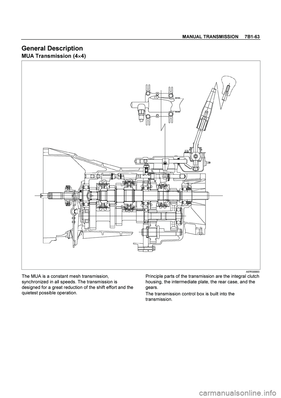
MANUAL TRANSMISSION 7B1-63
General Description
MUA Transmission (4�
�� �4)
A07R300003
The MUA is a constant mesh transmission,
synchronized in all speeds. The transmission is
designed for a great reduction of the shift effort and the
quietest possible operation.
Principle parts of the transmission are the integral clutch
housing, the intermediate plate, the rear case, and the
gears.
The transmission control box is built into the
transmission.
Page 3232 of 4264
7B1-68 MANUAL TRANSMISSION
19. Remove engine rear mount bolts fixing
transmission.
220R300009
20. Remove the middle part of transmission
crossmember (15) by removing four fixing bolts and
nuts.
501R30007
21. Take out the rear support rubber. 22. Remove starter (16). (Diesel engine only)
060L100070
23. Use the clutch release bearing remover 5-8840-
2291-0 (J-39207) to disconnect the clutch release
bearing from the clutch pressure plate. (6VE1 only)
220RW109
Release bearing disconnection
1. Pull the shift fork toward the transmission to
press the clutch release bearing against the
clutch.
2. Insert the clutch release bearing remover
between the wedge collar and the release
bearing.
3. Turn the remover to separate the release
bearing.
 to the
mainshaft (26).
The clutch hub face with the heavy boss must be
facing the 2nd gear side.
22")

Snap Ring Availability
Thickness Color Coding
1.80 mm (0.071 in) White
1.85")
 NOISY IN NEUTRAL
Checkpoint Trouble Cause Countermeasure
Replenish or replace the gear
oilInsufficient or improper g")


Replace the spring
Replace the bearing(s)
W")
 by removing four fixing bolts and")