Page 3149 of 4264
 Apply the engine oil to the 2nd needle bearing and the 2nd
gear.
2) Install the needle bearing and the 2nd gear to")
MSG MODEL 7B-31
Important Operations
2. Needle Bearing
3. 2nd Gear
1) Apply the engine oil to the 2nd needle bearing and the 2nd
gear.
2) Install the needle bearing and the 2nd gear to the
mainshaft.
The dog teeth of the 2nd gear must be facing the rear side
of the transmission.
5. 1st-2nd Synchronizer Assembly
1) Apply the engine oil to the clutch hub spline.
2) Install the synchronizer assembly to the mainshaft.
The outside sleeve heavy chamfering must be facing the
rear of the transmission.
1 Chamfer Angle = 30�
2 Chamfer Angle = 45�
7. Needle Bearing Collar
Use a bench press and the collar installer to install the needle
bearing collar.
Collar Installer : 5-8840-0178-0 (J-33851)
8. Needle Bearing
9. 1st Gear
1) Apply the engine oil to the 1st needle bearing and the 1st
gear.
2) Install the needle bearing and the gear to the mainshaft.
The dog teeth of the 1st gear must be facing the front side
of the transmission.
10. 1st Gear Thrust Washer
Install the thrust washer to the mainshaft.
The thrust washer oil groove must be facing the 1st gear side.
Page 3150 of 4264
 Apply the engine oil to the ball bearing inside
circumference.
2) Use a bench press and the bearing installer to install the
bearing.")
7B-32 MSG MODEL
11. Mainshaft Ball Bearing
1) Apply the engine oil to the ball bearing inside
circumference.
2) Use a bench press and the bearing installer to install the
bearing.
The bearing snap ring groove must be facing the front o
f
the transmission.
Bearing Installer : 5-8840-0015-0 (J-22912-01)
12. Needle Bearing
13. 3rd Gear
1) Apply the engine oil to the 3rd needle bearing and the 3rd
gear.
2) Install the needle bearing and the gear to the mainshaft.
The dog teeth of the 3rd gear must, be facing the front side
of the transmission.
15. 3rd-4th Synchronizer Assembly
1)
Apply the recommended lubricating oil to the clutch hub
spline.
2) Install the synchronizer assembly to the mainshaft.
The sleeve light chamfering
1 and the clutch hub heavy
boss
2 must be facing the rear of the transmission.
16. Mainshaft Snap Ring
1) Select the snap ring which will provide the minimum
clearance between the mainshaft and the snap ring.
There are four snap ring sizes available.
The snap rings are numbered to indicate their thickness.
Mainshaft and Snap Ring Clearance mm(in)
Standard
0 - 0.05 (0.002)
Snap Ring Availability mm(in)Thickness Identification Number
1.50 (0.059) 1
1.55 (0.061) 2
1.60 (0.063) 3
1.65 (0.065) 4
2) Use a pair of snap ring pliers to install the snap ring to the
mainshaft.
Page 3154 of 4264
 Apply the engine oil to the clutch hub spline.
2) Install the synchronizer assembly to the mainshaft.
The sleeve heavy chamfer
1")
7B-36 MSG MODEL
13. Rev.-5th Synchronizer Assembly
1) Apply the engine oil to the clutch hub spline.
2) Install the synchronizer assembly to the mainshaft.
The sleeve heavy chamfer
1 and the insert short side
2
must be facing to the rear side of the transmission.
14. Mainshaft Lock Nut and Washer
1) Install a new lock nut and washer to the mainshaft.
Never reinstall the used lock nut and washer.
2) Use the lock nut wrench to tighten the lock nut to the
specified torque.
Lock Nut Wrench : 5-8840-0353-0 (J-36629)
Lock Nut Torque N�m(kgf�m/lb�ft)
107.8 (11 / 79.6)
22. Counter Reverse Gear Nut and Washer
Tighten the counter gear lock nut to the specified torque.
Reverse Gear Nut Torque N�
m(kgf�
m/lb�
ft)
107.8 (11 / 79.6)
18. Thrust Washer and Lock Ball
23. Thrust Washer Thrust Ring
24. Thrust Ring Snap ring
1) Install the thrust washer with lock ball together with the
thrust ring to the mainshaft.
2) Use a pair of snap ring pliers to install the snap ring.
3) Use a thickness gauge to measure the clearance between
the 5th gear and the thrust washer.
5th Gear and Thrust Washer Clearance mm(in)
Standard
0.1 - 0.3 (0.004 - 0.012)
If required, replace the existing thrust washer with a new
thrust washer to bring the clearance to specification.
Page 3158 of 4264
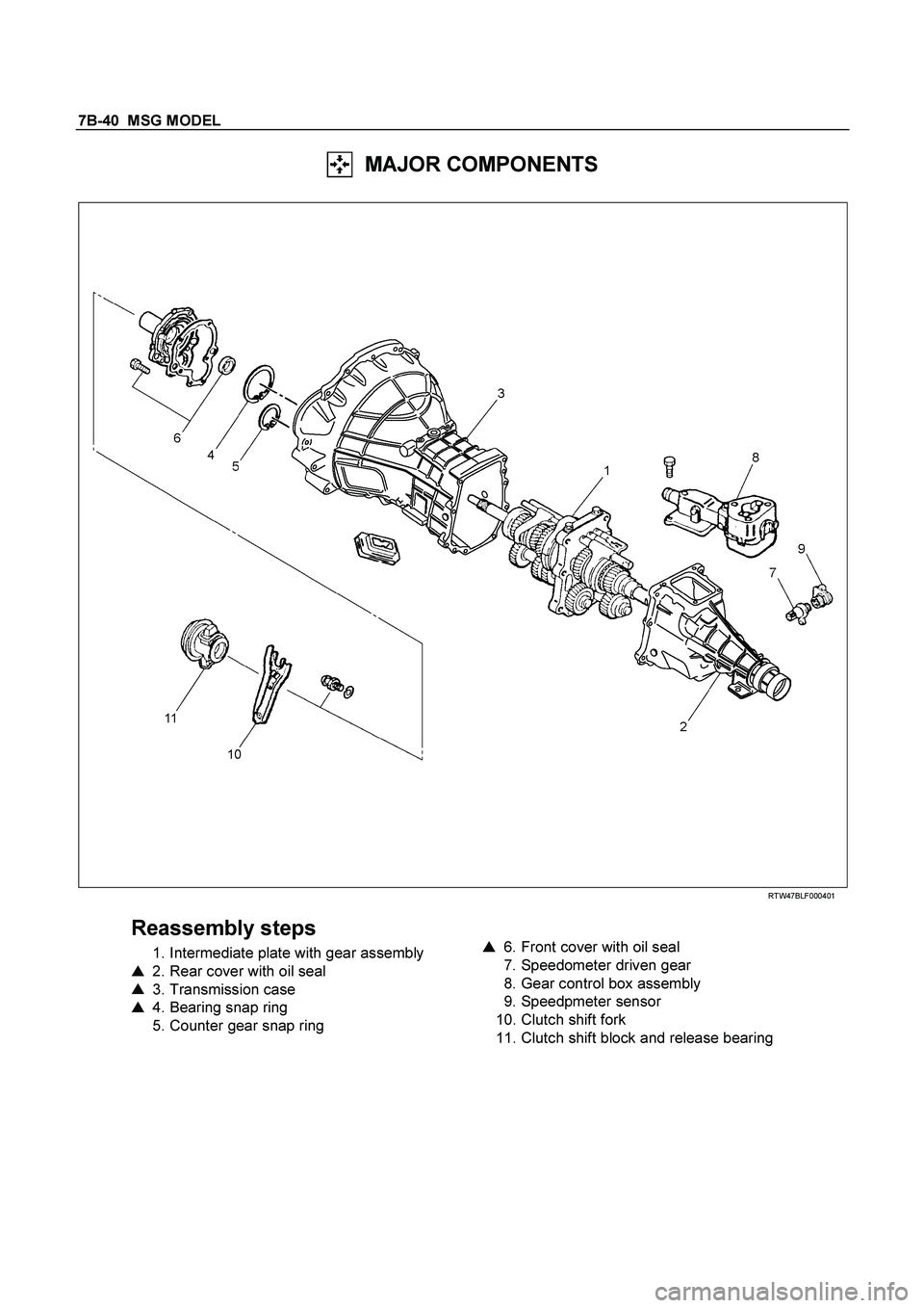
7B-40 MSG MODEL
MAJOR COMPONENTS
RTW47BLF000401
Reassembly steps
1. Intermediate plate with gear assembly
�
2. Rear cover with oil seal
�
3. Transmission case
�
4. Bearing snap ring
5. Counter gear snap ring
�
6. Front cover with oil seal
7. Speedometer driven gear
8. Gear control box assembly
9. Speedpmeter sensor
10. Clutch shift fork
11. Clutch shift block and release bearing
Page 3168 of 4264
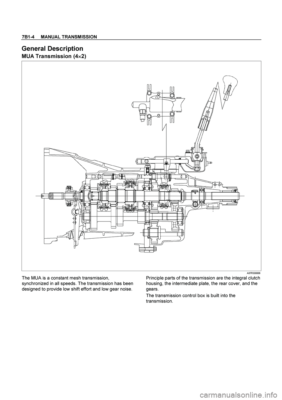
7B1-4 MANUAL TRANSMISSION
General Description
MUA Transmission (4�
�� �2)
A07R300006
The MUA is a constant mesh transmission,
synchronized in all speeds. The transmission has been
designed to provide low shift effort and low gear noise.
Principle parts of the transmission are the integral clutch
housing, the intermediate plate, the rear cover, and the
gears.
The transmission control box is built into the
transmission.
Page 3175 of 4264
MANUAL TRANSMISSION 7B1-11
17. Remove the middle part of transmission
crossmember (12) by removing four fixing bolts and
nuts.
501R300008
18. Take out the rear mount rubber (14).
19. Remove starter (15) (Diesel engine only).
060L100070
20. Use the clutch release bearing remover 5-8840-
2291-0 (J-39207) to disconnect the clutch release
bearing from the clutch pressure plate. (6VE1 only)
220RW109
Release bearing disconnection
1. Pull the shift fork toward the transmission to
press the clutch release bearing against the
clutch.
2. Insert the clutch release bearing remover
between the wedge collar and the release
bearing.
3. Turn the remover to separate the release
bearing.
Page 3176 of 4264
7B1-12 MANUAL TRANSMISSION
NOTE: Be sure not to insert the remover between the
wedge collar and the clutch.
220RW063
220RW064
220RW019
Legend
(1) Pressure Plate Assembly
(2) Release Bearing
(3) Wedge Collar
21. Remove transmission retaining nuts and bolts(16).
Remove transmission assembly (17) from the
vehicle.
Installation
1. Apply a thin coat of molybdenum disulfide grease to
the top gear shaft spline.
2. Slowly operate the transmission jack until the front
of transmission is aligned with the rear of the
engine.
The slope of the engine and the transmission must
be the same.
3. Align the top gear shaft spline with the clutch driven
plate spline.
Page 3179 of 4264
MANUAL TRANSMISSION 7B1-15
C24NE
RTW37BLF0002
220RS006
5. Apply a force of about 113N (26 Ib) to the tip of the
shift fork in the direction of the transmission to
engage the clutch pressure plate and release
bearing. (6VE1 only)
NOTE: A clicking sound is heard when the release
bearing and the tip of the diaphragm spring engage
each other.
Check to see if they are securely engaged by pushing
the tip of the shift fork toward the engine while applying
a force of about 25 N (5.5 lb). If the shift fork will not
move, then they are securely engaged.
 by removing four fixing bolts and
nuts.
501R300008
18. Take out the rear mount rubber (14).
19. Remov")
 Pressure Plate Assembly
(2) Release Bea")
 to the tip of the
shift fork in the direction of the transmission to
engage the clutch pres")