Page 3121 of 4264
MSG MODEL 7B-3
GENERAL DESCRIPTION
The MSG type transmission is fully synchronized 5-speed unit with blocking ring type synchronizers and a constant
mesh type reverse gear.
The unit consists principally of a case with an integral clutch housing, intermediate plate, rear cover and gears.
The top of the rear cover is a quadrant box containing the transmission control mechanism.
The case and rear cover are cast aluminum alloy to reduce weight.
Page 3128 of 4264
7B-10 MSG MODEL
3) Manually move the transmission as far as possible toward
the rear of the vehicle (into the space between the No.3
crossmember
3 and the floor panel 4 .
4) Lower the clutch housing end of the transmission toward the
transmission jack.
The rear of the transmission is supported by the No.3
crossmember at this time.
5) Firmly grasp the transmission rear cover (1st mechanic).
Raise the transmission jack toward the transmission (2nd
mechanic).
Carefully lower the transmission onto the transmission jack.
The transmission must be centered on the transmission
jack.
8. Carefully pull the transmission jack with the transmission
from beneath the vehicle.
Page 3129 of 4264

MSG MODEL 7B-11
Important Operations - Installation
Follow the removal procedure in the reverse order to perform
the installation procedure.
Pay careful attention to the important points during the
installation procedure.
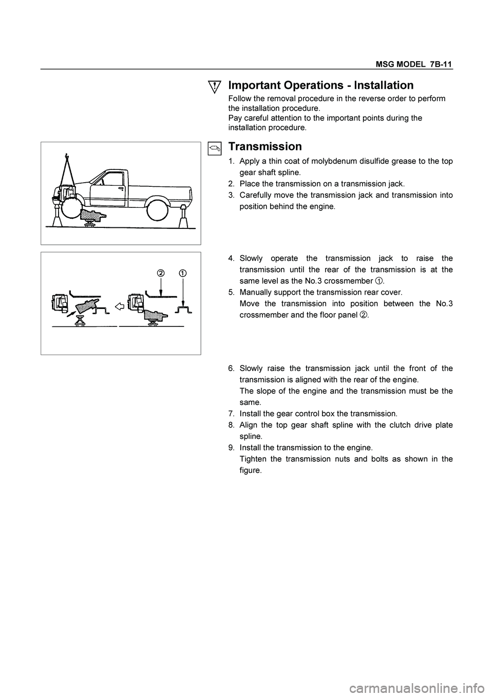
Transmission
1. Apply a thin coat of molybdenum disulfide grease to the top
gear shaft spline.
2. Place the transmission on a transmission jack.
3. Carefully move the transmission jack and transmission into
position behind the engine.
4. Slowly operate the transmission jack to raise the
transmission until the rear of the transmission is at the
same level as the No.3 crossmember
1 .
5. Manually support the transmission rear cover.
Move the transmission into position between the No.3
crossmember and the floor panel
2 .
6. Slowly raise the transmission jack until the front of the
transmission is aligned with the rear of the engine.
The slope of the engine and the transmission must be the
same.
7. Install the gear control box the transmission.
8. Align the top gear shaft spline with the clutch drive plate
spline.
9. Install the transmission to the engine.
Tighten the transmission nuts and bolts as shown in the
figure.
Page 3133 of 4264
MSG MODEL 7B-15
DISASSEMBLY
MAJOR COMPONENTS
RTW47BLF000301
Disassembly Steps
1. Clutch shift block and release bearing
2. Clutch shift fork
3. Speedometer sensor
4. Speedometer driven gear assembly
5. Gear control box assembly
�
6. Front cover with oil seal
�
7. Counter gear snap ring
�
8. Bearing snap ring
9. Rear cover with oil seal
10. Transmission case
11. Intermediate plate with gear assembly
Page 3139 of 4264

MSG MODEL 7B-21
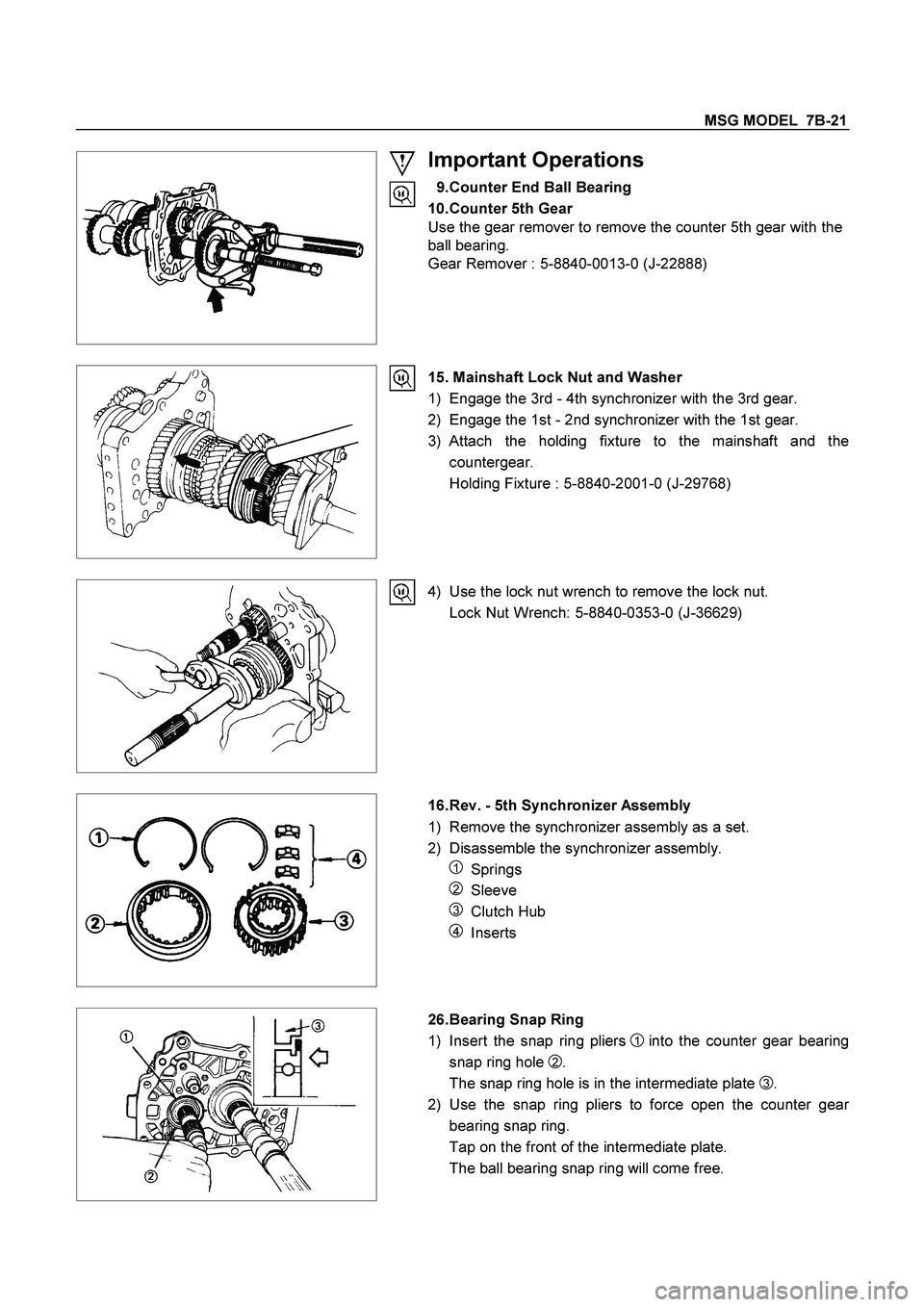
Important Operations
9. Counter End Ball Bearing
10. Counter 5th Gear
Use the gear remover to remove the counter 5th gear with the
ball bearing.
Gear Remover : 5-8840-0013-0 (J-22888)
15. Mainshaft Lock Nut and Washer
1) Engage the 3rd - 4th synchronizer with the 3rd gear.
2) Engage the 1st - 2nd synchronizer with the 1st gear.
3) Attach the holding fixture to the mainshaft and the
countergear.
Holding Fixture : 5-8840-2001-0 (J-29768)
4) Use the lock nut wrench to remove the lock nut.
Lock Nut Wrench: 5-8840-0353-0 (J-36629)
16. Rev. - 5th Synchronizer Assembly
1) Remove the synchronizer assembly as a set.
2) Disassemble the synchronizer assembly.
1 Springs
2 Sleeve
3 Clutch Hub
4 Inserts
26. Bearing Snap Ring
1) Insert the snap ring pliers
1 into the counter gear bearing
snap ring hole
2.
The snap ring hole is in the intermediate plate
3.
2) Use the snap ring pliers to force open the counter gea
r
bearing snap ring.
Tap on the front of the intermediate plate.
The ball bearing snap ring will come free.
Page 3142 of 4264
7B-24 MSG MODEL
Important Operations
1. Top Gear Shaft Snap Ring
2. Top Gear Shaft
3. Ball Bearing
1) Use a pair of snap ring pliers to remove the snap ring.
2) Use a bench press and the bearing remover to remove the
ball bearing.
Bearing Remover : 5-8840-0015-0 (J-22912-01)
7. 3rd - 4th Synchronizer Assembly
1) Remove the synchronizer assembly as a set.
2) Disassembly the synchronizer assembly.
1 Springs
2 Sleeve
3 Clutch Hub
4 Inserts
11. Mainshaft Ball Bearing
Use a bench press and the bearing remover to remove the ball
bearing.
Bearing Remover : 5-8840-0015-0 (J-22912-01)
17. 1st - 2nd Synchronizer Assembly
1) Remove the synchronizer assembly as a set.
2) Disassembly the synchronizer assembly.
1 Springs
2 Sleeve
3 Clutch Hub
4 Inserts
22. Rear Ball Bearing
24. Front Ball Bearing
Use a bench press and the bearing remover to remove the ball
bearing.
Bearing Removar : 5-8840-0015-0 (J-22912-01)
Page 3144 of 4264

7B-26 MSG MODEL
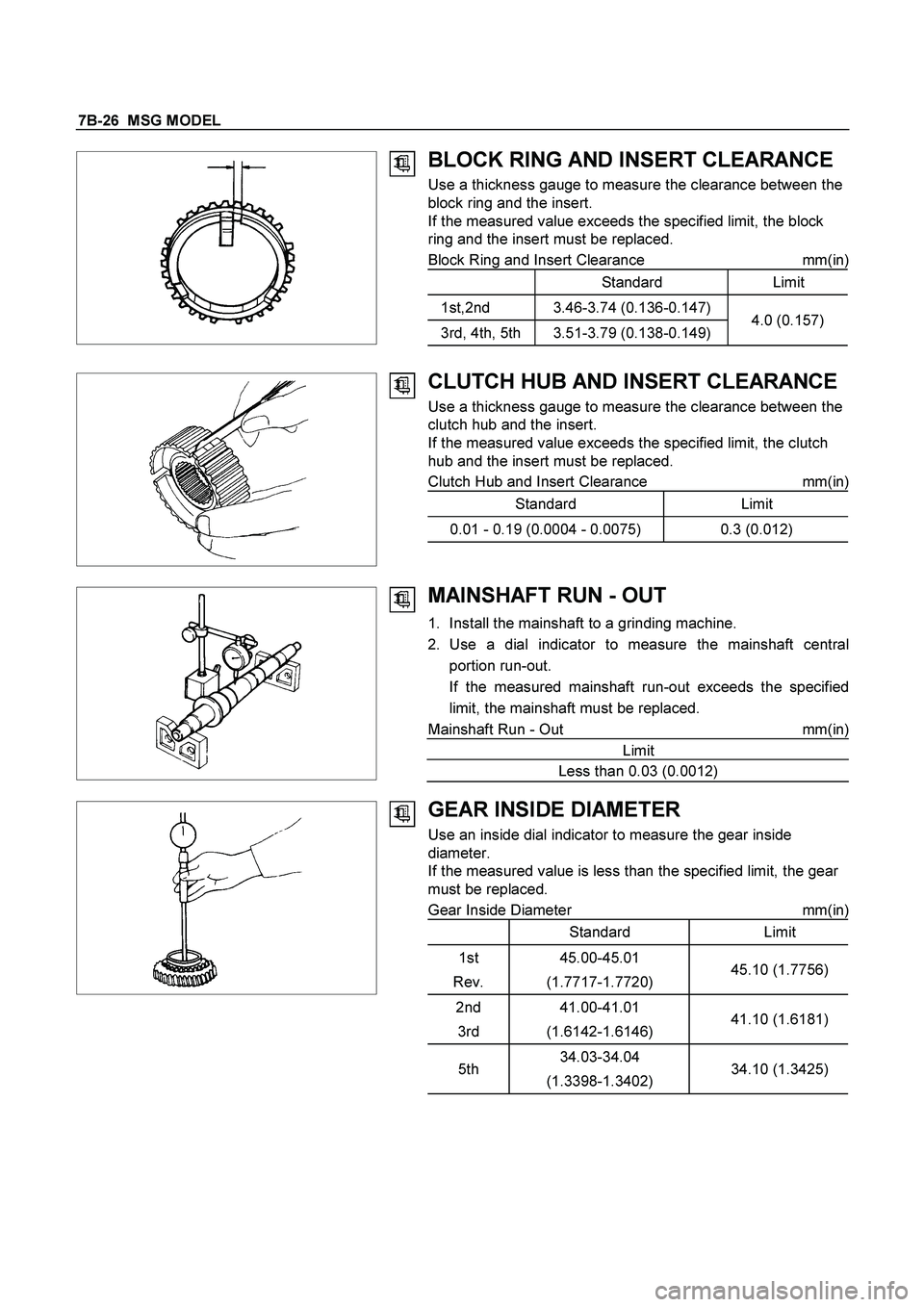
BLOCK RING AND INSERT CLEARANCE
Use a thickness gauge to measure the clearance between the
block ring and the insert.
If the measured value exceeds the specified limit, the block
ring and the insert must be replaced.
Block Ring and Insert Clearance mm(in)
Standard Limit
1st,2nd 3.46-3.74 (0.136-0.147)
3rd, 4th, 5th 3.51-3.79 (0.138-0.149)4.0 (0.157)
CLUTCH HUB AND INSERT CLEARANCE
Use a thickness gauge to measure the clearance between the
clutch hub and the insert.
If the measured value exceeds the specified limit, the clutch
hub and the insert must be replaced.
Clutch Hub and Insert Clearance mm(in)
Standard Limit
0.01 - 0.19 (0.0004 - 0.0075) 0.3 (0.012)
MAINSHAFT RUN - OUT
1. Install the mainshaft to a grinding machine.
2. Use a dial indicator to measure the mainshaft central
portion run-out.
If the measured mainshaft run-out exceeds the specified
limit, the mainshaft must be replaced.
Mainshaft Run - Out mm(in)
Limit
Less than 0.03 (0.0012)
GEAR INSIDE DIAMETER
Use an inside dial indicator to measure the gear inside
diameter.
If the measured value is less than the specified limit, the gear
must be replaced.
Gear Inside Diameter mm(in)
Standard Limit
1st
Rev.45.00-45.01
(1.7717-1.7720)45.10 (1.7756)
2nd
3rd41.00-41.01
(1.6142-1.6146)41.10 (1.6181)
5th34.03-34.04
(1.3398-1.3402)34.10 (1.3425)
Page 3145 of 4264
MSG MODEL 7B-27
REVERSE IDLER GEAR AND IDLER
GEAR SHAFT CLEARANCE
1. Use a micrometer to measure the idler gear shaft diameter.
2. Use an inside dial indicator to measure the idler gear inside
diameter.
3. Calculate the idler gear and idler gear shaft clearance.
Idler gear inside diameter - idler gear shaft diameter = idle
r
gear and idler gear shaft clearance.
If the measured value exceeds the specified limit, the idle
r
gear and/or the idler gear shaft must be replaced.
Idler Gear and Idler Gear Shaft Clearance mm(in)
Standard Limit
0.041 - 0.074 (0.0016 - 0.0029) 0.150 (0.0059)
CLUTCH HUB SPLINE PLAY
1. Set a dial indicator to the clutch hub to be measured.
2. Move the clutch hub as far as possible to both the right and
the left.
Note the dial indicator reading.
It the measured value exceeds the specified limit, the
clutch hub must be replaced.
Clutch Hub Spline Play mm(in
)
Standard Limit
0.019 (0 - 0.075) 0.20 (0.0079)