Page 2469 of 4264
ENGINE MECHANICAL (C24SE) 6A-49
Reassembly
Reassemble clutch assembly.
Disassembly
Disassemble clutch assembly to flywheel using 5-8840-2634-0
Torque Angle-Method
Clutch assembly to flywheel-17.6Nm/1.8 kgf �
m.
RTW46ASH002801
Oil Pan and Bearing Bridge
Removal
1. Remove the crossmember.
2. Shift downward the power steering unit (and front axle [4 �4 model only]).
3. Loosen fixing bolts.
4. Remove oil pan from oil pump and cylinder block.
5. Remove oil intake pipe, oil intake pipe bracket, and oil baffle plate.
6. Remove the bearing bridge.
Page 2472 of 4264

Installation
1. Install piston with con-rod by inserting with engine oil.
2. Coat piston rings with engine oil and compress with
piston ring comp")
6A-52 ENGINE MECHANICAL (C24SE)
Installation
1. Install piston with con-rod by inserting with engine oil.
2. Coat piston rings with engine oil and compress with
piston ring compressor.
Important!
Installation position:
Arrow / notch on piston head on timing side of engine
Beads on con-rod on clutch side
Torque-Angle Method
Piston to cylinder block.
Con-rod bearing cap to con-rod-35N�m (3.5 kgf�m) +45� to 60�
Important!
Use new bolts.
Installation
1. Install oil pan and cylinder head according to the
corresponding operations.
2. Install sealing Gasket or replace if damaged.
3. Install camshaft housing to cylinder head.
4. Install cylinder head according to the corresponding
operation.
Con-Rod
Removal
1. Remove piston with con-rod according to the
corresponding operation.
2. Disassemble con-rod piston assembly by pressing out
piston pin, using 5-8840-0468-0.
Installation
1. Slide guide drift (5-8840-0468-0) in horizontal position
through piston and con-rod as far as side plate stops.
2. Tighten bolts evenly so that the piston rests flush on the
rear plate.
3. Remove centre piece from guide drift and insert piston
bolts (lubricated) into guide drift.
Page 2497 of 4264
 6A-77
Cooling System
Radiator
Type: Cross-flow
Radiator core surface in cm
2: 2000
Cooling system capacity (in litres): 7.2
Anti-freeze Mixture
Anti-fr")
ENGINE MECHANICAL (C24SE) 6A-77
Cooling System
Radiator
Type: Cross-flow
Radiator core surface in cm
2: 2000
Cooling system capacity (in litres): 7.2
Anti-freeze Mixture
Anti-freeze Mixture
Required
Quantity Up to-10�
�� �C
Quantity in litres Up to-20�
�� �C
Quantity in litres Up to-30�
�� �C
Quantity in litres Up to-40�
�� �C
Quantity of litres
(in litres) Water
(80%) Anti-
Freeze
(20%) Water
(66%) Anti-
Freeze
(34%) Water
(56%) Anti-
Freeze
(44%) Water
(48%) Anti-
Freeze
(52%)
7.2 5.7 1.5 4.7 2.5 4.0 3.2 3.4 3.8
Cooling System (continued)
Fan
Type Visco Clutch Fan
Number of blades 5
Distribution of blades asymmetric
Diameter mm
Radiator cap
Boiling point 123�C
Opening pressure kPa (bar) 120 to 135 (1.20 to 1.35)
Thermostat
Start of opening 92�C
Fully opened 107�C
Type Bypassed
Idle Speeds, CO Content, Ignition
Adjustment
Applicable System Idle speed in min-1 (rpm)
Manual CO content
in vol. % Ignition timing in CA BTDC (adjustment
ensues at able speed,
ignition marks must align) with TDC
sensor measuring instrument:
Closed Loop System 825 *<0.4 *** 8 to 12
Open Loop System 825
**1.0+0.2
-0.5 *** 8 to 12
Note) * CO content adjustment not applicable.
** CO content adjustment refer to Section 6E1 (W/O catalytic converter system)
*** Ignition timing adjustment not possible.
Page 2506 of 4264
6A-86 ENGINE MECHANICAL (C24SE)
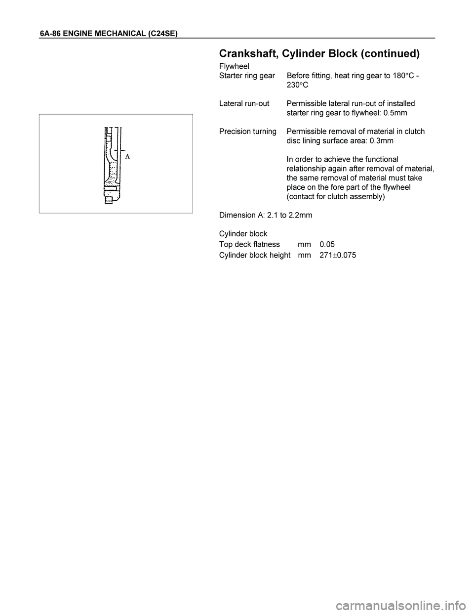
Crankshaft, Cylinder Block (continued)
Flywheel
Starter ring gear Before fitting, heat ring gear to 180�C -
230�C
Lateral run-out Permissible lateral run-out of installed
starter ring gear to flywheel: 0.5mm
Precision turning Permissible removal of material in clutch
disc lining surface area: 0.3mm
In order to achieve the functional
relationship again after removal of material,
the same removal of material must take
place on the fore part of the flywheel
(contact for clutch assembly)
Dimension A: 2.1 to 2.2mm
Cylinder block
Top deck flatness mm 0.05
Cylinder block height mm 271�0.075
Page 2511 of 4264

ENGINE COOLING 6B-1
SECTION 6B
ENGINE COOLING
CONTENTS
PAGE
General Description........................................................................................................ 6B- 2
Service Precaution......................................................................................................... 6B- 3
Diagnosis......................................................................................................................... 6B- 5
Draining and Refilling Cooling System ......................................................................... 6B- 6
Water Pump ..................................................................................................................... 6B- 7
Water Pump and Associated Parts ........................................................................... 6B- 7
Removal ...................................................................................................................... 6B- 7
Inspection ................................................................................................................... 6B- 7
Installation .................................................................................................................. 6B- 8
Thermostat ...................................................................................................................... 6B- 9
Removal ...................................................................................................................... 6B- 9
Inspection ................................................................................................................... 6B- 9
Installation .................................................................................................................. 6B- 9
Fan clutch with Cooling Fan .......................................................................................... 6B- 9
Inspection and Repair................................................................................................ 6B- 9
Radiator ........................................................................................................................... 6B-11
Radiator and Associated Parts ................................................................................. 6B-11
Removal ...................................................................................................................... 6B-11
Inspection ................................................................................................................... 6B-12
Installation .................................................................................................................. 6B-13
Main Data and Specifications ........................................................................................ 6B-13
Special Service Tool ....................................................................................................... 6B-14
Page 2515 of 4264
ENGINE COOLING 6B-5
Diagnosis
Engine Cooling Trouble
Condition Possible cause Correction
Engine overheating Low Engine Coolant level Replenish
Thermo mater unit faulty Replace
Faulty thermostat Replace
Faulty Engine Coolant temperature
sensor Repair or replace
Clogged radiator Clean or replace
Faulty radiator cap Replace
Low engine oil level or use of
improper engine oil Replenish or change oil
Clogged exhaust system Clean exhaust system or replace
faulty parts
Faulty Throttle Position sensor Replace throttle valve assembly
Open or shorted Throttle Position
sensor circuit Repair or replace
Damaged cylinder head gasket Replace
Loosen V-belt tension Adjust belt tension or replace.
Collapsed hoses Replace
Faulty Fan clutch Replace
Engine overcooling Faulty thermostat Replace
Engine slow to warm-up Faulty thermostat Replace
Thermo unit faulty Replace
Page 2519 of 4264

ENGINE COOLING 6B-9
Thermostat
Removal
1. Disconnect battery ground cable.
2. Drain engine coolant from the radiator and engine.
3. Disconnect radiator hose from the inlet pipe.
4. Remove thermostat housing.
5. Remove thermostat from thermostat housing.
Inspection
Suspend the thermostat in a water-filled container using thin
wire. Place a thermometer next to the thermostat.
Do not directly heat the thermostat.
Gradually increase the water temperature. Stir the water so
that the entire water is same temperature.
Confirm the temperature when the valve first begins to open.
Valve opening temperature 92�
�� �C (197.6�
�� �F)
Confirm the temperature when the valve is fully opened.
Valve full open temperature 107�
�� �C(224.6�
�� �F)
Make necessary repair and parts replacement if extreme wear
or damage is found during inspection.
Installation
1. Before installing thermostat, coat sealing surface with
silicon grease.
2. Install O-ring.
3. Install thermostat housing and tighten bolts to the specified
torque.
Torque: 15 N�
�� �m (1.5 kgf�
�� �m)
4. Installation rubber hose.
5. Replenish engine coolant (EC).
6. Start engine and check for EC leakage.
Fan Clutch with Cooling Fan
Inspection and Repair
Make necessary correction or parts replacement if wear,
damage or any other abnormal condition are found through
inspection.
Visually inspect for damage, leak (silicon grease) or other
abnormal conditions.
1. Inspection (on-vehicle)
1) Turn the fan clutch by hand when in a low temperature
condition before starting the engine, and confirm that it
can be turned readily.
2) Start the engine to warm it up until the temperature at the
fan clutch portion gets to around 80�C. Then stop the
engine and confirm that the fan clutch can be turned with
considerable effort (clutch torque) when turned by hand.
Page 2520 of 4264
6B-10 ENGINE COOLING
If the fan clutch rotates more readily, however, this
indicates that the silicon grease is leaking internally.
Replace the fan clutch with a new one.
2. Inspection (in unit)
Warm up the bimetal of the fan clutch by using the heat gun
until the temperature gets to about 80�C when measured
with the thermistor. Then confirm that the fan clutch can be
turned with considerable effort (clutch torque).
If the fan clutch retates more readily at this time, this
indicates that the silicon grease is leaking internally.
Replace the fan clutch with a new one.
 6A-49
Reassembly
Reassemble clutch assembly.
Disassembly
Disassemble clutch assembly to flywheel using 5-8840-2634-0
Torque Angle-Method
Clutch assemb")