Page 1939 of 4264

ENGINE COOLING (6VE1 3.5L) 6B-15
Drive Belt and Cooling Fan
Drive Belt and Associated Parts
015RW005
Legend (4) Water Pump and Cooling Fan Pulley
(1) Crankshaft Pulley (5) Idle Pulley
(2) Generator (6) Tension Pulley
(3) Power Steering Pump (7) Drive Belt
The drive belt adjustment is not required as automatic
drive belt tensioner is equipped.
Inspection
Check drive belt for wear or damage, and replace with a
new one as necessary.
Installation
Install cooling fan assembly and tighten bolts/nuts to the
specified torque.
Torque : 25 N�
�� �m (2.5 kg�
�� �m/18 lb ft) for fan pulley
and fan bracket.
Torque : 10 N�
�� �m (1.0 kg�
�� �m/7 lb ft) for fan and
clutch assembly.
NOTE: Fan belts for 6VE1 Gasoline Engine mounted on
98MY (UX) have been brought into one. As a result, the
rotating direction of a fan belt is opposite to the direction
of cooling fan for 92 to 97MY 6VD1 with no
interchangeability.
Therefore, incorrect installation of a fan may cause the
air for cooling to flow in the opposite direction, this
resulting in the poor performance of the air-conditione
r
and a rise temperature in engine cooling water.
Page 1978 of 4264
6D3-6 STARTING AND CHARGING SYSTEM (6VE1 3.5L)
Disassembled View
065R100012
Legend (7) Housing
(1) Lead Wire (8) Over Running Clutch
(2) Through Bolt (9) Return Spring
(3) Yoke Assembly (10) Steel Ball
(4) Yoke Cover (11) Idle Pinion
(5) Brush and Brush Holder (12) Retainer
(6) Armature (13) Magnetic Switch
Page 1979 of 4264
STARTING AND CHARGING SYSTEM (6VE1 3.5L) 6D3-7
Disassembly
1. Remove the lead wire (1) from the magnetic switch.
2. Remove the through bolts (2).
065RY00053
Legend
(1) Lead Wire
(2) Through Bolt
3. Remove the yoke from the magnetic.
4. Remove the yoke cover.
5. Use the long nose pliers to remove the brush and
brush holder.
065RY00054
065RY00055
Legend
(1) Spring
(2) Brush
6. Remove the armature.
7. Remove the housing.
8. Remove the overrunning clutch from the housing.
065RY00056
Page 1980 of 4264
6D3-8 STARTING AND CHARGING SYSTEM (6VE1 3.5L)
9. Remove the return spring from the magnetic switch.
065R100014
10. Remove the steel ball from the overrunning clutch.
065RY00058
11.Remove the idle pinion from the magnetic switch.
065R100015
12. Remove the retainer from the magnetic switch.
065R100016
13. Remove the magnetic switch.
Page 1983 of 4264

STARTING AND CHARGING SYSTEM (6VE1 3.5L) 6D3-11
Brush Spring
Use spring balancer to measure the spring setting force
when remove the spring from the brush.
Standard: 17.65–23.54 N (38.9–51.9 lb)
Limit: 11.77 N (25.9 lb)
Magnetic Switch
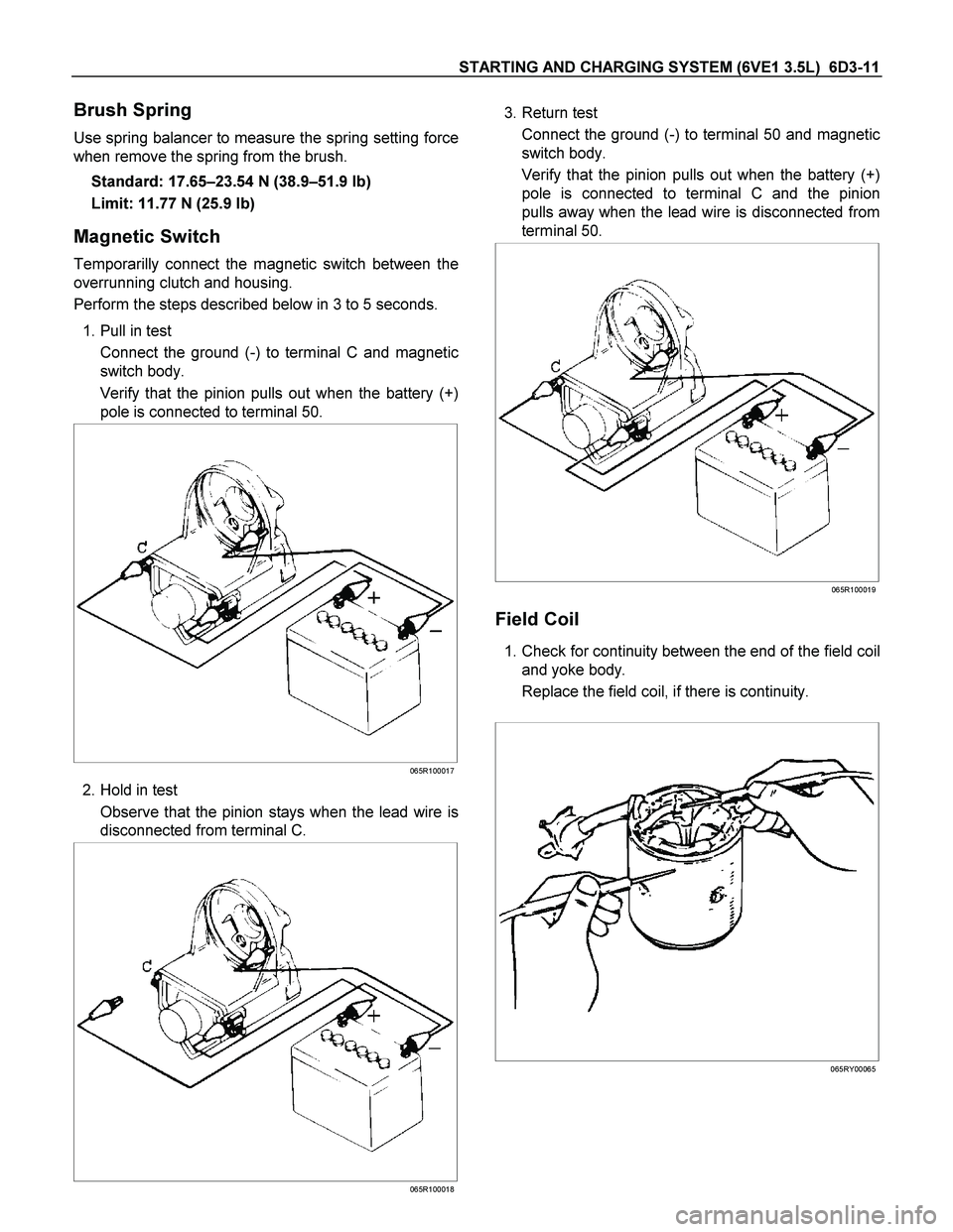
Temporarilly connect the magnetic switch between the
overrunning clutch and housing.
Perform the steps described below in 3 to 5 seconds.
1. Pull in test
Connect the ground (-) to terminal C and magnetic
switch body.
Verify that the pinion pulls out when the battery (+)
pole is connected to terminal 50.
065R100017
2. Hold in test
Observe that the pinion stays when the lead wire is
disconnected from terminal C.
065R100018
3. Return test
Connect the ground (-) to terminal 50 and magnetic
switch body.
Verify that the pinion pulls out when the battery (+)
pole is connected to terminal C and the pinion
pulls away when the lead wire is disconnected from
terminal 50.
065R100019
Field Coil
1. Check for continuity between the end of the field coil
and yoke body.
Replace the field coil, if there is continuity.
065RY00065
Page 1984 of 4264
6D3-12 STARTING AND CHARGING SYSTEM (6VE1 3.5L)
2. Check continuity between the lead wire of terminal
C and brush.
Replace the yoke assembly, if there is no continuity.
065RY00066
Overrunning Clutch
1. Visual check for excessive wear or damage.
2. Test the pinion rotation, it must rotate smoothly
when rotated clockwise and it shouldn't rotate when
turned counterclockwise.
065RY00067
Bearing
1. Inspect excessive wear or damage.
Replace the bearing if an abnormal noise is heard
under normal operating condition.
065RY00068
Reassembly
To install, follow the removal steps in the reverse order,
noting the following points:
Grease application places
Bearing in rear cover
Gears in reduction gear
Sliding portion of pinion
Page 2023 of 4264
3.5L ENGINE DRIVEABILITY AND EMISSIONS 6E-27
CONNECTOR LIST
No. Connector face No. Connector face
B-24
Green
Meter-B C-108
WhiteJ/B E1
B-56
White
J/B I4 C-109
SilverBody-LH ; ground
B-58
Black
Check connector E-2
Magnetic clutch
B-62
White
Ignition switch (IGSUB : G1) E-6
Fuel injector
B-63
White
Ignition switch (IGSUB : G2) E-7
Fuel injector
B-68
Immobilizer E-8
Fuel injector
C-2
Silver
Engine room-RH ground E-9
Fuel injector
C-24
Triple pressure switch E-51
Fuel injector
C-94
Gray TCM-(A) E-52
Fuel injector
C-107
White
J/B E2 E-53
Ignition coil
Page 2073 of 4264

3.5L ENGINE DRIVEABILITY AND EMISSIONS 6E-77
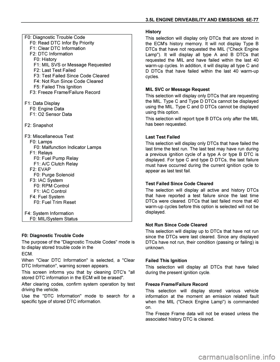
F0: Diagnostic Trouble Code
F0: Read DTC Infor By Priority
F1: Clear DTC Information
F2: DTC Information
F0: History
F1: MIL SVS or Message Requested
F2: Last Test Failed
F3: Test Failed Since Code Cleared
F4: Not Run Since Code Cleared
F5: Failed This Ignition
F3: Freeze Frame/Failure Record
F1: Data Display
F0: Engine Data
F1: O2 Sensor Data
F2: Snapshot
F3: Miscellaneous Test
F0: Lamps
F0: Malfunction Indicator Lamps
F1: Relays
F0: Fuel Pump Relay
F1: A/C Clutch Relay
F2: EVAP
F0: Purge Solenoid
F3: IAC System
F0: RPM Control
F1: IAC Control
F4: Fuel System
F0: Fuel Trim Reset
F4: System Information
F0: MIL/System Status
F0: Diagnostic Trouble Code
The purpose of the "Diagnostic Trouble Codes" mode is
to display stored trouble code in the
ECM.
When "Clear DTC Information" is selected, a "Clea
r
DTC Information", warning screen appears.
This screen informs you that by cleaning DTC's "all
stored DTC information in the ECM will be erased".
After clearing codes, confirm system operation by test
driving the vehicle.
Use the "DTC Information" mode to search for a
specific type of stored DTC information.
History
This selection will display only DTCs that are stored in
the ECM's history memory. It will not display Type B
DTCs that have not requested the MIL ("Check Engine
Lamp"). It will display all type A and B DTCs tha
t
requested the MIL and have failed within the last 40
warm-up cycles. In addition, it will display all type C and
D DTCs that have failed within the last 40 warm-up
cycles.
MIL SVC or Message Request
This selection will display only DTCs that are requesting
the MIL. Type C and Type D DTCs cannot be displayed
using the MIL. Type C and D DTCs cannot be displayed
using this option.
This selection will report type B DTCs only after the MIL
has been requested.
Last Test Failed
This selection will display only DTCs that have failed the
last time the test run. The last test may have run during
a previous ignition cycle of a type A or type B DTC is
displayed. For type C and type D DTCs, the last failure
must have occurred during the current ignition cycle to
appear as last test fail.
Test Failed Since Code Cleared
The selection will display all active and history DTCs
that have reported a test failure since the last time
DTCs were cleared. DTCs that last failed more that 40
warm-up cycles before this option is selected will not be
displayed.
Not Run Since Code Cleared
This selection will display up to DTCs that have not run
since the DTCs were last cleared. Since any displayed
DTCs have not run, their condition (passing or failing) is
unknown.
Failed This Ignition
This selection will display all DTCs that have failed
during the present ignition cycle.
Freeze Frame/Failure Record
This selection will display stored various vehicle
information at the moment an emission related faul
t
when the MIL ("Check Engine Lamp") is commanded
on.
The Freeze Frame data will not be erased unless the
associated history DTC is cleared.