2004 ISUZU TF SERIES clutch
[x] Cancel search: clutchPage 1370 of 4264
6D – 32 ENGINE ELECTRICAL
MAGNETIC SWITCH
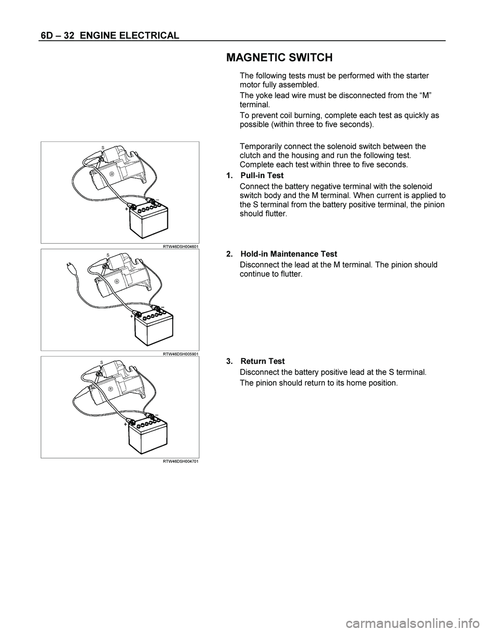
The following tests must be performed with the starter
motor fully assembled.
The yoke lead wire must be disconnected from the “M”
terminal.
To prevent coil burning, complete each test as quickly as
possible (within three to five seconds).
RTW46DSH004601
Temporarily connect the solenoid switch between the
clutch and the housing and run the following test.
Complete each test within three to five seconds.
1. Pull-in Test
Connect the battery negative terminal with the solenoid
switch body and the M terminal. When current is applied to
the S terminal from the battery positive terminal, the pinion
should flutter.
RTW46DSH005901
2. Hold-in Maintenance Test
Disconnect the lead at the M terminal. The pinion should
continue to flutter.
RTW46DSH004701
3. Return Test
Disconnect the battery positive lead at the S terminal.
The pinion should return to its home position.
Page 1378 of 4264
6E–6 4JA1/4JH1 ENGINE DRIVEABILITY AND EMISSIONS
Circuit Description ..................................... 6E-268
Diagnostic Aids .......................................... 6E-268
Diagnostic Trouble Code (DTC) P0645
(Symptom Code 4) (Flash Code 46) A/C
Compressor Relay Circuit Voltage Low ... 6E-269
Diagnostic Trouble Code (DTC) P0645
(Symptom Code 8) (Flash Code 46) A/C
Compressor Relay Circuit Voltage High .. 6E-272
DIAGNOSTIC TROUBLE CODE (DTC) P0703
(SYMPTOM CODE A) (FLASH CODE 25)
BRAKE SWITCH CIRCUIT MALFUNCTION 6E-273
DIAGNOSTIC TROUBLE CODE (DTC) P0703
(SYMPTOM CODE B) (FLASH CODE 25)
BRAKE SWITCH CIRCUIT MALFUNCTION 6E-273
Circuit Description ..................................... 6E-274
Diagnostic Aids .......................................... 6E-274
Diagnostic Trouble Code (DTC) P0703
(Symptom Code A) (Flash Code 25) Brake
Switch Circuit Malfunction ....................... 6E-274
Diagnostic Trouble Code (DTC) P0703
(Symptom Code B) (Flash Code 25)
Brake Switch Circuit Malfunction ............. 6E-278
DIAGNOSTIC TROUBLE CODE (DTC) P0704
(SYMPTOM CODE 6) (FLASH CODE 57)
CLUTCH SWITCH INPUT CIRCUIT
MALFUNCTION ....................................... 6E-281
Circuit Description ..................................... 6E-281
Diagnostic Aids .......................................... 6E-281
Diagnostic Trouble Code (DTC) P0704
(Symptom Code 6) (Flash Code 57)
Clutch Switch Input Circuit Malfunction ... 6E-282
DIAGNOSTIC TROUBLE CODE (DTC) P1105
(SYMPTOM CODE 1) (FLASH CODE 86)
BAROMETRIC PRESSURE SENSOR
CIRCUIT HIGH INPUT ............................ 6E-285
DIAGNOSTIC TROUBLE CODE (DTC) P1105
(SYMPTOM CODE 2) (FLASH CODE 86)
BAROMETRIC PRESSURE SENSOR
CIRCUIT LOW INPUT ............................. 6E-285
Circuit Description ..................................... 6E-285
Diagnostic Aids .......................................... 6E-285
Diagnostic Trouble Code (DTC) P1105
(Symptom Code 1) (Flash Code 86) Barometric
Pressure Sensor Circuit High Input ......... 6E-285
Diagnostic Trouble Code (DTC) P1105
(Symptom Code 2) (Flash Code 86) Barometric
Pressure Sensor Circuit Low Input .......... 6E-285
DIAGNOSTIC TROUBLE CODE (DTC) P1120
(SYMPTOM CODE 1) (FLASH CODE 21)
PEDAL/THROTTLE POSITION SENSOR
CIRCUIT HIGH INPUT ............................ 6E-287
DIAGNOSTIC TROUBLE CODE (DTC) P1120
(SYMPTOM CODE 7) (FLASH CODE 21)PEDAL/THROTTLE POSITION SENSOR
VOLTAGE SUPPLY CIRCUIT HIGH INPUT 6E-287
DIAGNOSTIC TROUBLE CODE (DTC) P1120
(SYMPTOM CODE 9) (FLASH CODE 21)
PEDAL/THROTTLE POSITION SENSOR
VOLTAGE SUPPLY CIRCUIT LOW INPUT 6E-287
DIAGNOSTIC TROUBLE CODE (DTC) P1120
(SYMPTOM CODE D) (FLASH CODE 21)
PEDAL/THROTTLE POSITION SENSOR
BRAKE SWITCH ERROR ....................... 6E-287
DIAGNOSTIC TROUBLE CODE (DTC) P1120
(SYMPTOM CODE E) (FLASH CODE 21)
PEDAL/THROTTLE POSITION SENSOR
IDLE POSITION SWITCH ERROR ......... 6E-287
Circuit Description ...................................... 6E-288
Diagnostic Aids .......................................... 6E-288
Diagnostic Trouble Code (DTC) P1120
(Symptom Code 1) (Flash Code 21)
Pedal/Throttle Position Sensor
Circuit High Input ..................................... 6E-288
Diagnostic Trouble Code (DTC) P1120
(Symptom Code 7) (Flash Code 21)
Pedal/Throttle Position Sensor Voltage
Supply Circuit High Input ......................... 6E-293
Diagnostic Trouble Code (DTC) P1120
(Symptom Code 9) (Flash Code 21)
Pedal/Throttle Position Sensor Voltage
Supply Circuit Low Input .......................... 6E-295
Diagnostic Trouble Code (DTC) P1120
(Symptom Code D) (Flash Code 21)
Pedal/Throttle Position Sensor Brake
Switch Error ............................................. 6E-298
Diagnostic Trouble Code (DTC) P1120
(Symptom Code E) (Flash Code 21)
Pedal/Throttle Position Sensor Idle
Position Switch Error ............................... 6E-300
DIAGNOSTIC TROUBLE CODE (DTC) P1173
(SYMPTOM CODE 3) (FLASH CODE 22) FUEL
REDUCTION CAUSED BY HIGH COOLANT
TEMPERATURE ...................................... 6E-302
DIAGNOSTIC TROUBLE CODE (DTC) P1173
(SYMPTOM CODE 7) (FLASH CODE 22) FUEL
REDUCTION CAUSED BY HIGH FUEL
TEMPERATURE ...................................... 6E-302
DIAGNOSTIC TROUBLE CODE (DTC) P1173
(SYMPTOM CODE A) (FLASH CODE 22) FUEL
REDUCTION CAUSED BY LOW FUEL
TEMPERATURE ...................................... 6E-302
Circuit Description ...................................... 6E-302
Diagnostic Aids .......................................... 6E-302
Diagnostic Trouble Code (DTC) P1173
(Symptom Code 3) (Flash Code 22) Fuel
Reduction Caused By High Coolant
Page 1385 of 4264
4JA1/4JH1 ENGINE DRIVEABILITY AND EMISSIONS 6E–13
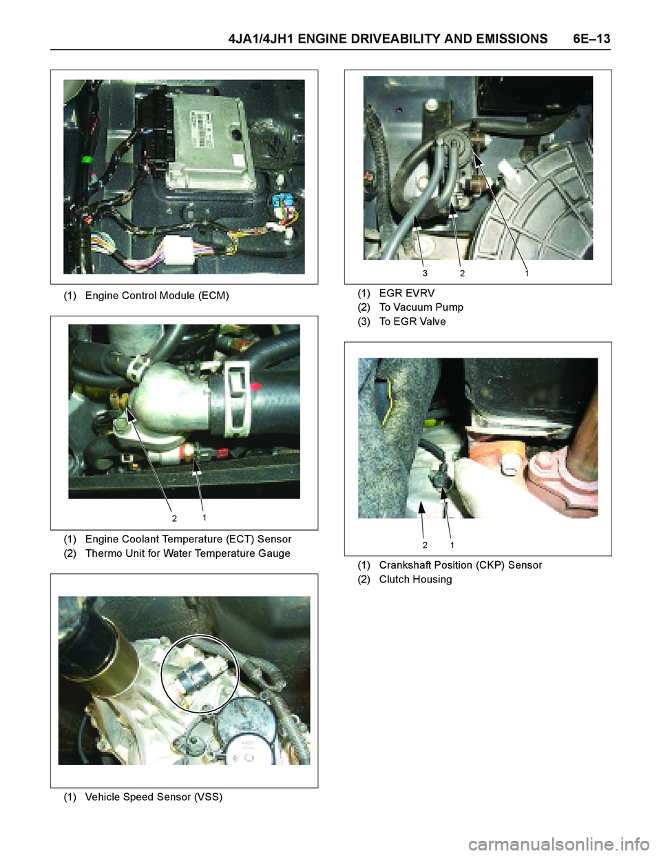
(1) Engine Control Module (ECM)
(1) Engine Coolant Temperature (ECT) Sensor
(2) Thermo Unit for Water Temperature Gauge
(1) Vehicle Speed Sensor (VSS)
21
(1) EGR EVRV
(2) To Vacuum Pump
(3) To EGR Valve
(1) Crankshaft Position (CKP) Sensor
(2) Clutch Housing
321
12
Page 1412 of 4264
6E–40 4JA1/4JH1 ENGINE DRIVEABILITY AND EMISSIONS
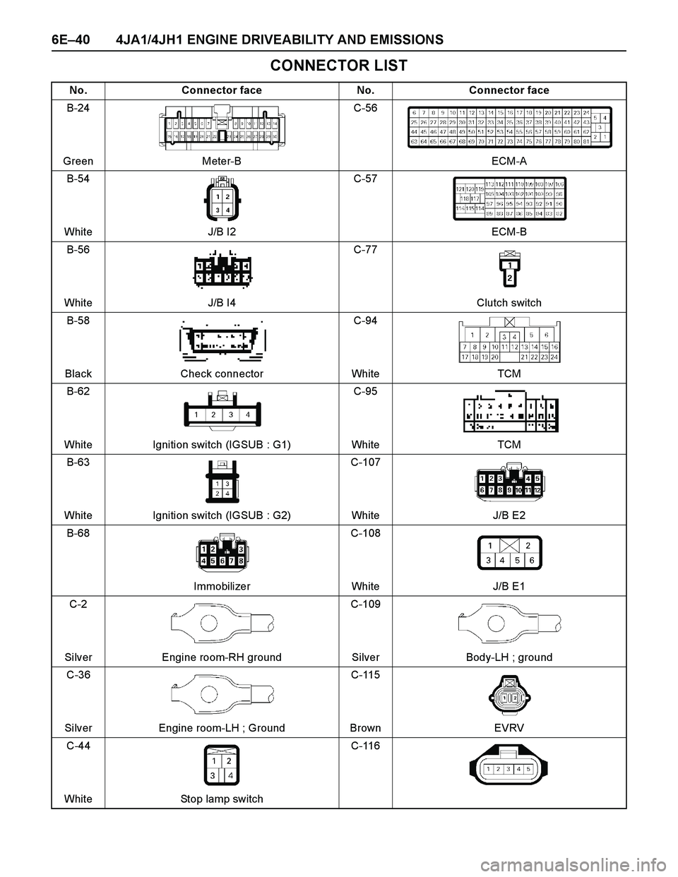
CONNECTOR LIST
No. Connector face No. Connector face
B-24
Green Meter-BC-56
ECM-A
B-54
White J/B I2C-57
ECM-B
B-56
White J/B I4C-77
Clutch switch
B-58
Black Check connectorC-94
White TCM
B-62
White Ignition switch (IGSUB : G1)C-95
White TCM
B-63
White Ignition switch (IGSUB : G2)C-107
White J/B E2
B-68
ImmobilizerC-108
White J/B E1
C-2
Silver Engine room-RH groundC-109
Silver Body-LH ; ground
C-36
Silver Engine room-LH ; GroundC-115
Brown EVRV
C-44
White Stop lamp switchC-116
Page 1413 of 4264
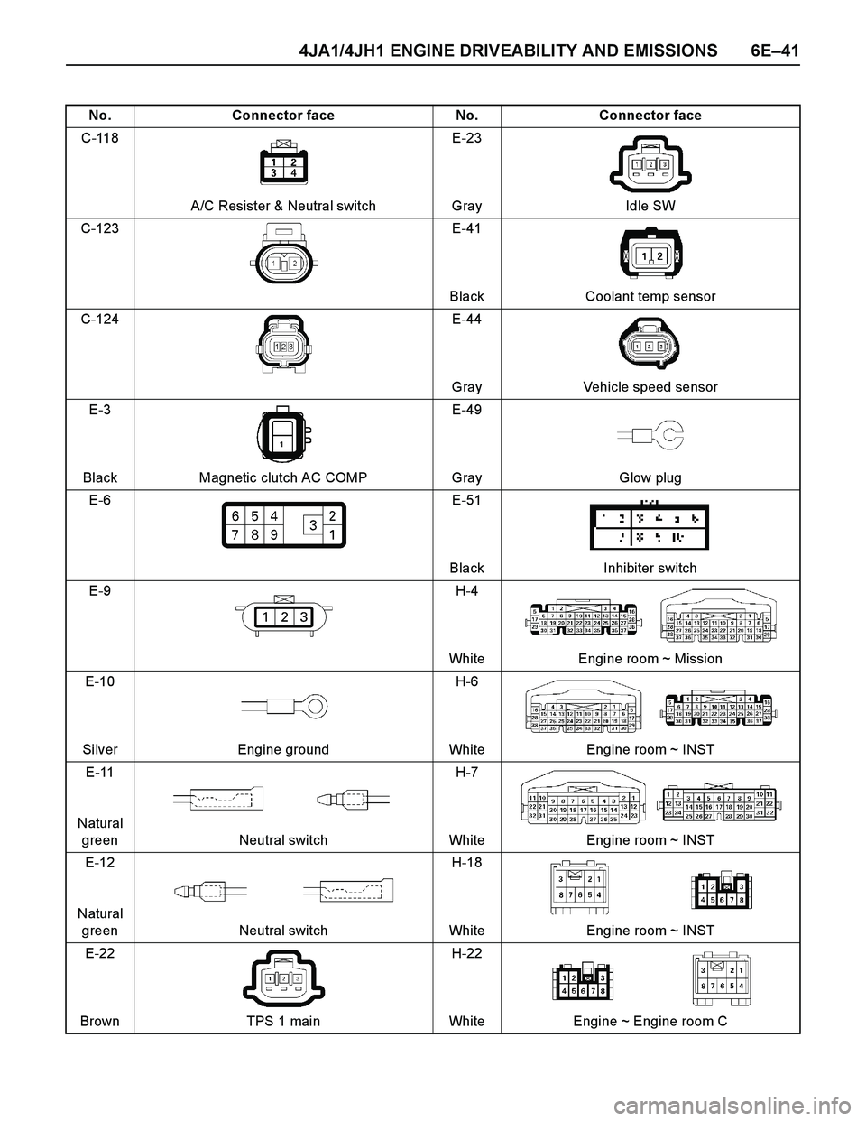
4JA1/4JH1 ENGINE DRIVEABILITY AND EMISSIONS 6E–41
No. Connector face No. Connector face
C-118
A/C Resister & Neutral switchE-23
Gray Idle SW
C-123 E-41
Black Coolant temp sensor
C-124 E-44
Gray Vehicle speed sensor
E-3
Black Magnetic clutch AC COMPE-49
Gray Glow plug
E-6 E-51
Black Inhibiter switch
E-9 H-4
White Engine room ~ Mission
E-10
Silver Engine groundH-6
White Engine room ~ INST
E-11
Natural
green Neutral switchH-7
White Engine room ~ INST
E-12
Natural
green Neutral switchH-18
White Engine room ~ INST
E-22
Brown TPS 1 mainH-22
White Engine ~ Engine room C
Page 1425 of 4264
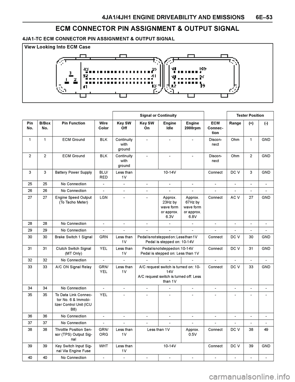
4JA1/4JH1 ENGINE DRIVEABILITY AND EMISSIONS 6E–53
ECM CONNECTOR PIN ASSIGNMENT & OUTPUT SIGNAL
4JA1-TC ECM CONNECTOR PIN ASSIGNMENT & OUTPUT SIGNA L
View Looking Into ECM Case
Signal or Continuity Tester Position
Pin
No. B/Box
No.Pin Function Wire
ColorKey SW
OffKey SW
OnEngine
IdleEngine
2000rpmECM
Connec-
tionRange (+) (-)
1 1 ECM Gro und BLK Continuity
with
gro und---Discon-
ne ctOhm 1 GND
2 2 ECM Gro und BLK Continuity
with
gro und---Discon-
ne ctOhm 2 GND
3 3 Batte ry Powe r Supply BLU/
REDLess than
1V10-14V Connect DC V 3 GND
25 25 No Conne ctio n - - - - - - - - -
26 26 No Conne ctio n - - - - - - - - -
27 27 Engine Spee d Output
(To Ta cho Me te r)LGN - - Approx.
23Hz by
w a v e fo rm
or approx.
6.3V Approx.
67Hz by
wave form
or approx.
6.8V Co nnect AC V 27 GND
28 28 No Conne ctio n - - - - - - - - -
29 29 No Conne ctio n - - - - - - - - -
30 30 Brake Switch 1 Signal GRN Less than
1VPedal is not stepped on: Less than 1V
Pedal is stepped on: 10-14VCo nnect DC V 30 GND
31 31 Clutch Switch Signal
(MT Only )YEL Less than
1VPedal is not stepped on: 10-14V
Pedal is stepped on: Less than 1VCo nnect DC V 31 GND
32 32 No Conne ctio n - - - - - - - - -
33 33 A/C ON Signa l Re la y GRN/
YELLess than
1VA/C re que st switch is turne d on: 10-
14V
A/C request switch is turned off: Less
than 1VCo nnect DC V 33 GND
34 34 No Conne ctio n - - - - - - - - -
35 35 To Da ta Link Co nnec-
tor No. 6 & Immobi-
lize r Contro l Unit (ICU
B8)YEL--------
36 36 No Conne ctio n - - - - - - - - -
37 37 No Conne ctio n - - - - - - - - -
38 38 Throttle Po sitio n Sen-
so r (TPS) Output Sig-
na lGRN/
ORGLess than
1VLess than 1V Approx.
0.5VCo nnect DC V 38 49
39 39 Key Sw itch Input Sig-
nal Via Engine FuseWHT Less than
1V10-14V Co nnect DC V 39 GND
40 40 No Conne ctio n - - - - - - - - -
Page 1430 of 4264
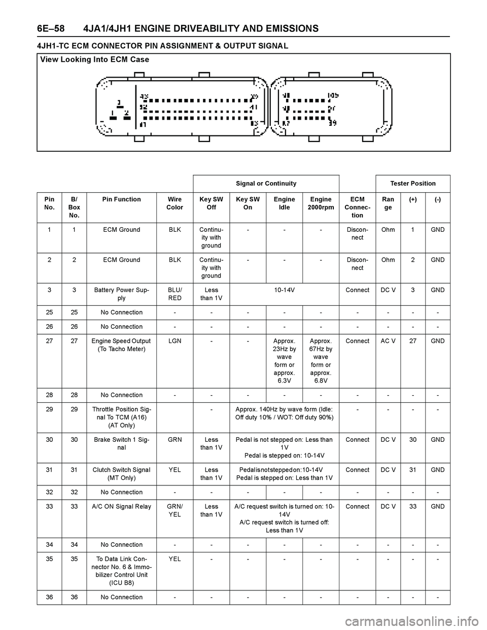
6E–58 4JA1/4JH1 ENGINE DRIVEABILITY AND EMISSIONS
4JH1-TC ECM CONNECTOR PIN ASSIGNMENT & OUTPUT SIGNA L
View Looking Into ECM Case
Signal or Continuity Tester Position
Pin
No. B/
Box
No.Pin Function Wire
ColorKey SW
OffKey SW
OnEngine
IdleEngine
2000rpmECM
Connec-
tionRan
ge(+) (-)
1 1 ECM Gro und BLK Co ntinu-
ity with
ground---Discon-
ne ctOh m 1 GND
2 2 ECM Gro und BLK Co ntinu-
ity with
ground---Discon-
ne ctOh m 2 GND
3 3 Batte ry Powe r Sup-
plyBLU/
REDLe ss
tha n 1V10-14V Co nnect DC V 3 GND
2525No Connection---------
2626No Connection---------
27 27 Engine Spee d Output
(To Ta cho Mete r)LGN - - Approx .
23Hz by
wave
fo rm or
approx.
6.3V Approx.
67Hz by
wave
fo rm or
approx.
6.8V Co nnect AC V 27 GND
2828No Connection---------
29 29 Throttle Positio n Sig-
na l To TCM (A16)
(AT Only )- Appro x . 140Hz by wav e fo rm (Idle:
Off duty 10% / WOT: Off duty 90%)- ---
30 30 Bra ke Switch 1 Sig-
na lGRN Le ss
tha n 1VPedal is not stepped on: Less than
1V
Pedal is stepped on: 10-14VCo nnect DC V 30 GND
31 31 Clutch Switch Signa l
(MT Only )YEL Less
tha n 1VPedal is not stepped on: 10-14V
Pe da l is ste ppe d o n: Le ss tha n 1VCo nnect DC V 31 GND
3232No Connection---------
33 33 A/C ON Signa l Rela y GRN/
YELLe ss
tha n 1VA/C request switch is turned on: 10-
14V
A/C reque st switch is turne d off:
Less than 1VCo nnect DC V 33 GND
3434No Connection---------
35 35 To Data Link Co n-
necto r No. 6 & Immo-
bilize r Co ntrol Unit
(ICU B8)YEL--------
3636No Connection---------
Page 1461 of 4264
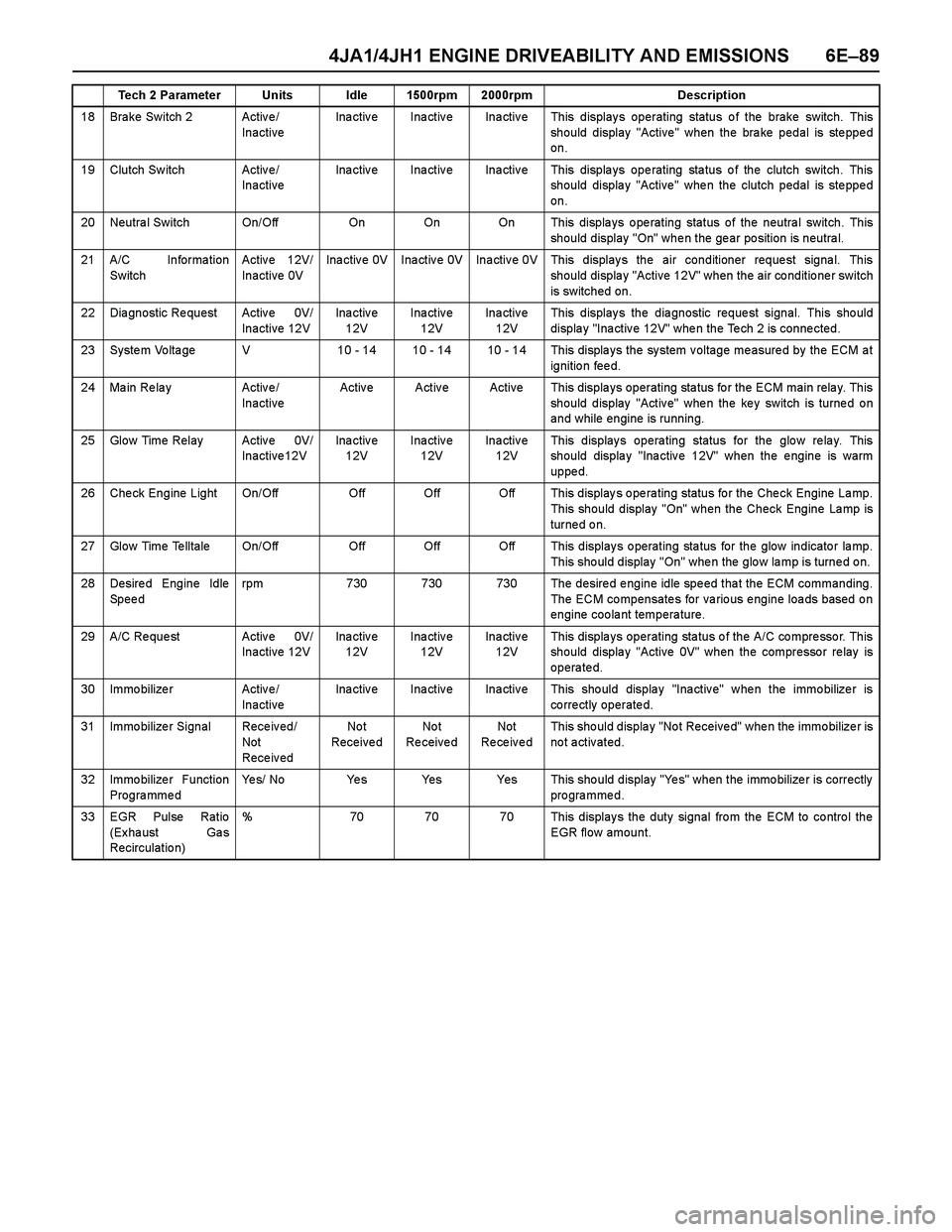
4JA1/4JH1 ENGINE DRIVEABILITY AND EMISSIONS 6E–89
18 Brake Switch 2 Active/
InactiveInactive Inactive Inactive This displays operating status of the brake switch. This
should display "Active" when the brake pedal is stepped
on.
19 Clutch Sw itch Activ e /
InactiveInactive Inactive Inactive This displays operating status of the clutch switch. This
should display "Active" when the clutch pedal is stepped
on.
20 Neutra l Switch On/Off On On On This displa ys o pe rating status of the neutra l switch. This
should display "On" when the gear position is neutral.
21 A/C Informa tion
SwitchActive 12V/
Inactive 0VInactive 0V Inactive 0V Inactive 0V This displays the air conditioner request signal. This
should display "Active 12V" when the air conditioner switch
is switched on.
22 Dia gnostic Re quest Activ e 0V/
Inactive 12VIna ctiv e
12VInactive
12VIna ctiv e
12VThis display s the dia gnostic reque st signal. This sho uld
display "Inactive 12V" when the Tech 2 is connected.
23 System Voltage V 10 - 14 10 - 14 10 - 14 This displays the system voltage measured by the ECM at
ignition feed.
24 Ma in Re la y Activ e /
InactiveActive Active Active This displays operating status for the ECM main relay. This
should display "Active" when the key switch is turned on
and while engine is running.
25 Glow Time Relay Activ e 0V/
Inactive12VIna ctiv e
12VInactive
12VIna ctiv e
12VThis displays operating status for the glow relay. This
should display "Inactive 12V" when the engine is warm
uppe d.
26 Check Engine Light On/Off Off Off Off This displays operating status for the Check Engine Lamp.
This should display "On" when the Check Engine Lamp is
turned on.
27 Glow Time Telltale On/Off Off Off Off This displays operating status for the glow indicator lamp.
This sho uld display "On" whe n the glo w la mp is turne d o n.
28 Desired Engine Idle
Speedrpm 730 730 730 The desired engine idle speed that the ECM commanding.
The ECM compensates for various engine loads based on
engine coolant temperature.
29 A/C Re que st Activ e 0V/
Inactive 12VIna ctiv e
12VInactive
12VIna ctiv e
12VThis displays operating status of the A/C compressor. This
should display "Active 0V" when the compressor relay is
operated.
30 Immo bilize r Activ e /
InactiveInactive Inactive Inactive This should display "Inactive" when the immobilizer is
correctly operated.
31 Immo bilize r Signal Rece iv ed/
Not
Rece iv edNo t
Receive dNo t
Re ceive dNot
Re ce iv e dThis sho uld displa y "No t Receive d" whe n the immo bilize r is
not activated.
32 Immo bilize r Function
ProgrammedYes/ No Yes Yes Yes This should display "Yes" when the immobilizer is correctly
programmed.
33 EGR Pulse Ratio
(Ex ha ust Ga s
Recirculatio n)% 70 70 70 This displays the duty signal from the ECM to control the
EGR flow amount. Tech 2 Parameter Units Idle 1500rpm 2000rpm Description