Page 3228 of 4264
7B1-64 MANUAL TRANSMISSION
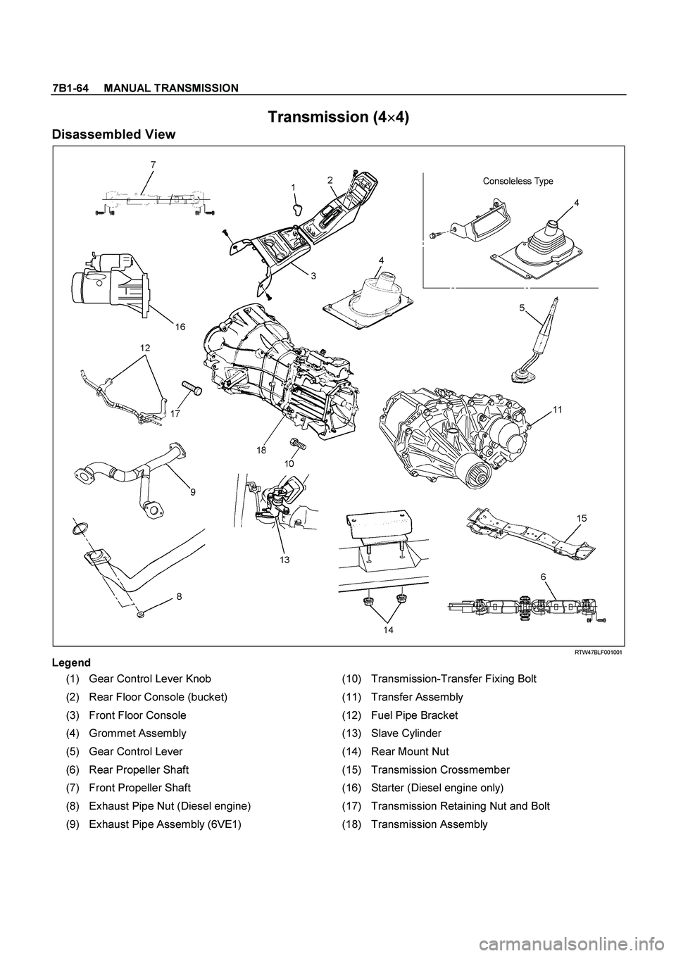
Transmission (4�
�� �
4)
Disassembled View
RTW47BLF001001
Legend
(1) Gear Control Lever Knob (10) Transmission-Transfer Fixing Bolt
(2) Rear Floor Console (bucket) (11) Transfer Assembly
(3) Front Floor Console (12) Fuel Pipe Bracket
(4) Grommet Assembly (13) Slave Cylinder
(5) Gear Control Lever (14) Rear Mount Nut
(6) Rear Propeller Shaft (15) Transmission Crossmember
(7) Front Propeller Shaft (16) Starter (Diesel engine only)
(8) Exhaust Pipe Nut (Diesel engine) (17) Transmission Retaining Nut and Bolt
(9) Exhaust Pipe Assembly (6VE1) (18) Transmission Assembly
Page 3230 of 4264
7B1-66 MANUAL TRANSMISSION
6. Remove gear control lever (5).
7. Raise and support vehicle with suitable stands.
8. Remove rear propeller shaft (6).
NOTE: Apply alignment marks on the flange at the
differential side.
9. Remove front propeller shaft (7).
NOTE: Apply alignment marks on the flange at both
front and rear sides.
401RS023
10. Loosen the front exhaust pipe fixing nuts (8) at the
engine side but not remove them. (Diesel engine
only)
150R300004
11. Remove the exhaust pipe (9). (6VE1 only)
RTW37ASH000101
12. Disconnect harness connectors and clips on the
transfer.
�
Actuator connector
�
Car Speed Sensor
810R300069
Legend
(1) Neutral Switch Connector: Transmission
(2) Back up Switch Connector
(3) Speed Sensor Connector
(4) Actuator Connector
(5) 2W - 4W Switch Connector
(6) Neutral Switch Connector: Transfer
Page 3231 of 4264
MANUAL TRANSMISSION 7B1-67
13. Remove transmission-transfer fixing bolts (10), and
remove the transfer assembly (11) from the
transmission.
14. Disconnect harness connectors and clips on the
transmission.
�
Neutral switch; Transmission
� Back up Switch
� 2W-4W Switch
�
Neutral Switch; Transfer
15. Remove the fuel pipe brackets (12) with pipes from
the transmission (18).
Diesel engine
220R300012
Legend
(1) Bolt
(2) Nut
(3) Fuel Pipe Assembly
6VE1, C24NE
Scan-2
16. Remove slave cylinder (13) and put aside it.
220LV019
17. Support transmission with a transmission jack.
220RS0001
18. Remove engine rear mount nuts (14) from
transmission crossmember (15).
Page 3232 of 4264
7B1-68 MANUAL TRANSMISSION
19. Remove engine rear mount bolts fixing
transmission.
220R300009
20. Remove the middle part of transmission
crossmember (15) by removing four fixing bolts and
nuts.
501R30007
21. Take out the rear support rubber. 22. Remove starter (16). (Diesel engine only)
060L100070
23. Use the clutch release bearing remover 5-8840-
2291-0 (J-39207) to disconnect the clutch release
bearing from the clutch pressure plate. (6VE1 only)
220RW109
Release bearing disconnection
1. Pull the shift fork toward the transmission to
press the clutch release bearing against the
clutch.
2. Insert the clutch release bearing remover
between the wedge collar and the release
bearing.
3. Turn the remover to separate the release
bearing.
Page 3233 of 4264
MANUAL TRANSMISSION 7B1-69
NOTE: Be sure not to insert the remover between the
wedge collar and the clutch.
220RW063
220RW064
220RW019
Legend
(1) Pressure Plate Assembly
(2) Release Bearing
(3) Wedge Collar
24. Remove transmission retaining nuts and bolts(17).
Remove transmission assembly (18) from the
vehicle.
Installation
1. Apply a thin coat of molybdenum disulfide grease to
the top gear shaft spline.
2. Slowly operate the transmission jack until the front
of transmission is aligned with the rear of the
engine.
The slope of the engine and the transmission must
be the same.
3. Align the top gear shaft with the clutch driven plate
spline.
Page 3234 of 4264
7B1-70 MANUAL TRANSMISSION
4. Install the transmission assembly (18) to the engine.
Tighten the transmission nuts and bolts as shown in
the figure.
Diesel engine
RTW37BLF000901
Page 3236 of 4264
7B1-72 MANUAL TRANSMISSION
RTW37BLF000201
5. Apply a force of about 113N (26 Ib) to the tip of the
shift fork in the direction of the transmission to
engage the clutch pressure plate and release
bearing. (6VE1 only)
NOTE: A clicking sound is heard when the release
bearing and the tip of the diaphragm spring engage
each other.
Check to see if they are securely engaged by pushing
the tip of the shift fork toward the engine while applying
a force of about 25 N (5.5 lb). If the shift fork will not
move, then they are securely engaged.
220RS006
Page 3237 of 4264
.(Diesel engine)
NOTE: Tighten the lower bolt temporarily.
After installing the fuel pipe assembly, tighten the bolt to
the specified torque")
MANUAL TRANSMISSION 7B1-73
6. Install starter(16).(Diesel engine)
NOTE: Tighten the lower bolt temporarily.
After installing the fuel pipe assembly, tighten the bolt to
the specified torque.
Torque: 76 N�
�� �m (7.7 kg�
�� �m/56 lb�
�� �ft)
7. Install the rear support rubber on the transmission
and tighten the bolts to the specified torque.
Torque: 50 N�
�� �m (5.1 kg�
�� �m/37 lb�
�� �ft)
8. Install the middle part of transmission crossmember
(15) and bolts.
Tighten the nuts to the specified torque.
Torque: 67 N�
�� �m (6.8 kg�
�� �m/49 lb�
�� �ft)
9. Install engine rear mount nuts (14).
Torque: 52 N�
�� �m (5.3 kg�
�� �m/38 lb�
�� �ft)
Remove the transmission jack from transmission
side.
10. Apply grease to top hole portion of the shift fork.
Install slave cylinder (13) and tighten the bolts to the
specified torque.
Torque: 76 N�
�� �m (7.7 kg�
�� �m/56 lb�
�� �ft)
11. Install the fuel pipe brackets on the transmission.
Install the fuel pipe assembly to the fuel pipe
brackets
Torque: Bolt & Nut 76 N�
�� �m (7.7 kg�
�� �m/56 lb�
�� �ft)
Nut 37 N�
�� �m (3.8 kg�
�� �m/28 lb�
�� �ft)
Diesel engine
220R300012
Legend
(1) Bolt
(2) Nut
(3) Fuel Pipe Assembly
6VE1, C24NE
Scan-2
12. Connect transmission harness connectors and clips.
Connector: transfer neutral switch, 2W - 4W switch,
backup switch, transmission neutral switch.
810R300069
Legend
(1) Neutral Switch Connector: Transmission
(2) Backup Switch Connector
(3) Speed Sensor Connector
(4) Actuator Connector
(5) 2W - 4W Switch connector
(6) Neutral Switch Connector: Transfer
13. Apply grease (BESCO L2 or equivalent) on the
splined portion of the output shaft.
14. Connect the transfer to the transmission.
.
7. Raise and support vehicle with suitable stands.
8. Remove rear propeller shaft (6).
NOTE: Apply alignment marks on the fl")
, and
remove the transfer assembly (11) from the
transmission.
14. Disconnect harness connectors and clips on th")
 by removing four fixing bolts and")
 Pressure Plate Assembly
(2) Release B")
 to the engine.
Tighten the transmission nuts and bolts as shown in
the figure.
Diesel engine
RTW37BLF000901")
 to the tip of the
shift fork in the direction of the transmission to
engage the clutch pressure pl")