Page 3113 of 4264
HEATER AND AIR CONDITIONING 1-103
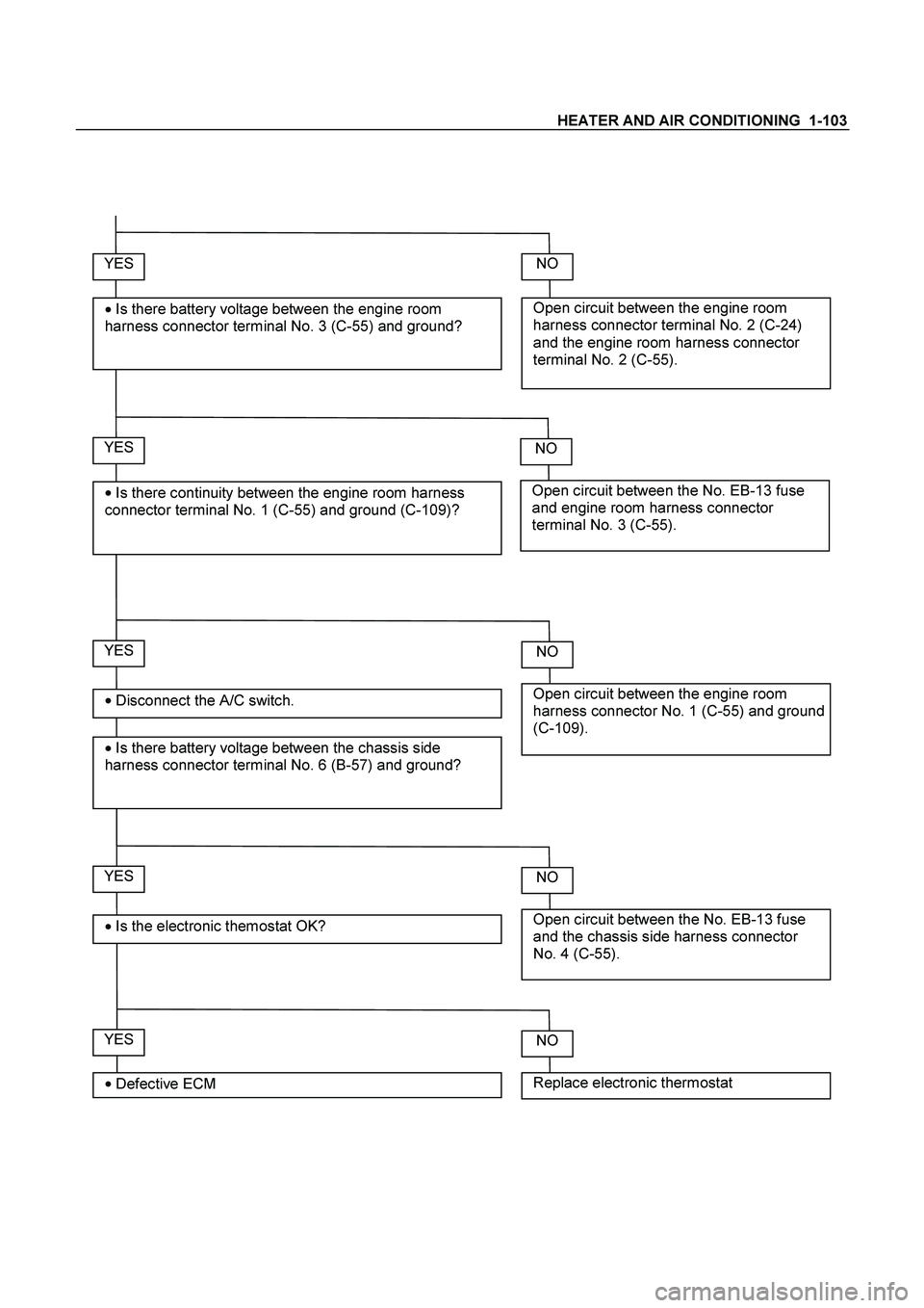
YES
�
Disconnect the A/C switch.
�
Is there battery voltage between the chassis side
harness connector terminal No. 6 (B-57) and ground?
Open circuit between the engine room
harness connector terminal No. 2 (C-24)
and the engine room harness connector
terminal No. 2 (C-55).
NO YES
�
Is there battery voltage between the engine room
harness connector terminal No. 3 (C-55) and ground?
Open circuit between the No. EB-13 fuse
and engine room harness connector
terminal No. 3 (C-55).
NO YES
�
Is there continuity between the engine room harness
connector terminal No. 1 (C-55) and ground (C-109)?
Open circuit between the engine room
harness connector No. 1 (C-55) and ground
(C-109).
NO
YES
�
Is the electronic themostat OK? Open circuit between the No. EB-13 fuse
and the chassis side harness connector
No. 4 (C-55).
NO
YES
�
Defective ECM Replace electronic thermostat
NO
Page 3125 of 4264

MSG MODEL 7B-7
REMOVAL AND INSTALLATION
Read this Section carefully before performing any removal and installation procedure. This Section gives you
important points as well as the order of operation. Be sure that you understand everything in this Section before
you begin.
Important Operations - Removal
Battery Cable
Disconnect the negative (-) cable from the battery terminal.
Engine Hood
Apply setting marks to the engine hood and the engine hood
hinges before removing the engine hood.
Gear Shift Lever
1. Place the gear shift lever in the neutral position.
2. Remove the gear shift lever knob.
3. Remove the front console assembly.
4. Remove the gear shift lever grommet and dust cover.
5. Remove the gear shift lever cover bolts.
6. Remove the gear shift lever.
Note:
Cover the shift lever hole to prevent the entry of foreign
material into the transmission.
Lifting the Vehicle
1. Jack up the vehicle.
2. Place chassis stands at the front and the rear of the
vehicle.
Transmission Oil Draining
1. Remove the transmission oil drain plug.
2. Replace the drain plug after draining the oil.
Page 3127 of 4264
MSG MODEL 7B-9
Engine Lifting Hanger
1. Attach the engine lifting hanger to the front portion of the
engine.
2.
Attach the lifting wire to both ends of the engine lifting
hanger.
Starter Motor
Remove the starter motor motor from the engine rear plate.
Transmission
1. Support the transmission with a transmission jack.
2. Remove the engine rear mounting bracket bolts and nuts
1
from the transmission 2.
3. Remove the bracket from No.3 crossmember.
4. Loosen the nuts for the rear mounting rubber.
5. Remove the rear mounting rubber
3 from the transmission
4.
6. Remove the gear control box from the transmission.
7. Remove the transmission from the engine.
The removal of the transmission will require the cooperative
efforts of two mechanics.
1) Remove the transmission nuts and bolts
1 from the
engine rear plate.
2) Place a transmission jack
2 beneath the transmission .
Do not raise the transmission jack.
Page 3129 of 4264

MSG MODEL 7B-11
Important Operations - Installation
Follow the removal procedure in the reverse order to perform
the installation procedure.
Pay careful attention to the important points during the
installation procedure.
Transmission
1. Apply a thin coat of molybdenum disulfide grease to the top
gear shaft spline.
2. Place the transmission on a transmission jack.
3. Carefully move the transmission jack and transmission into
position behind the engine.
4. Slowly operate the transmission jack to raise the
transmission until the rear of the transmission is at the
same level as the No.3 crossmember
1 .
5. Manually support the transmission rear cover.
Move the transmission into position between the No.3
crossmember and the floor panel
2 .
6. Slowly raise the transmission jack until the front of the
transmission is aligned with the rear of the engine.
The slope of the engine and the transmission must be the
same.
7. Install the gear control box the transmission.
8. Align the top gear shaft spline with the clutch drive plate
spline.
9. Install the transmission to the engine.
Tighten the transmission nuts and bolts as shown in the
figure.
Page 3131 of 4264

MSG MODEL 7B-13
Starter Motor
1. Install the starter motor to the engine rear plate.
2. Tighten the starter motor bolts to the specified torque.
Starter Motor Torque N�
m (kgf�
m/lb�
ft)
78 (8.0 / 58)
Slave Cylinder
Install the slave cylinder to the transmission case.
Slave Cylinder Bolt Torque N�
m (kgf�
m/lb�
ft
)
78 (8.0 / 58)
Harness Connector
Connect the back up light switch connector and speedometer
sensor connector.
Rear Propeller Shaft (Single Shaft Type)
1. Insert the splined yoke 1 with the propeller shaft into the
transmission main shaft spline
2 .
2. Install the propeller shaft flange yoke
3 to the drive pinion
side.
3. Tighten the propeller shaft flange yoke bolt to the specified
torque.
Propeller Shaft Flange Yoke Bolt Torque N�m (kgf�m/lb�ft)
M8 : 35.3 (3.6 / 26)
M10 : 62.7 (6.4 / 46.3)
Rear Propeller Shaft (Dual Shaft Type)
1. Place the center bearing and retainer 1 together with the
1st propeller shaft
2 and 2nd propeller shaft 7 on the No.4
crossmember
3.
2. Insert the splined yoke
4into the transmission main shaft
spline
5.
3. Tighten the center bearing retainer bolts
6 to the specified
torque.
Center Bearing Retainer Bolt Torque N�
m (kgf�
m/lb�
ft)
60.8 (6.2 / 44.8)
4. Connect the 2nd propeller shaft
7 and drive pinion side 8.
Be sure to align the setting marks applied at disassembly.
5. Tighten the coupling bolts to the specified torque.
Propeller Shaft Flange Yoke Bolt
Torque N�
m (kgf�
m/lb�
ft)
M8 : 35.3 (3.6 / 26)
M10 : 62.7 (6.4 / 46.3)
Page 3132 of 4264
7B-14 MSG MODEL
Exhaust Pipe
1. Install the exhaust pipe to the exhaust manifold and the
2nd exhaust pipe.
2. Install the exhaust pipe bracket to the transmission case.
Gear Shift Lever
1. Replenish the transmission case with the specified engine
oil.
Transmission Case Oil lit(US gal.)
1.55 (0.41)
2. Install the gear shift lever to the gear control box.
3. Tighten the gear shift lever cover bolts to the specified
torque.
Shift Lever Cover Bolt Torque N�
m(kgf�
m/lb�
ft)
19.6 (2.0 / 14.5)
4. Install the dust cover and the grommet.
5. Install the front console assembly.
6. Install the gear shift lever knob.
Lowering the Vehicle
1. Place a jack beneath the vehicle.
2. Raise the jack to remove the chassis stands.
3. Lower the vehicle to the ground.
Engine Hood
Align the setting marks(applied at removal)on the engine hood
and the engine hood hinges to install the engine hood.
Battery Cable
Connect the negative (-) cable to the battery terminal.
Page 3146 of 4264
7B-28 MSG MODEL
BALL BEARING PLAY
Use a dial indicator to measure the ball bearing play.
Ball Bearing Play mm(in)
Limit
0.2 (0.0079)
FRONT COVER OIL SEAL
Oil Seal Replacement
Oil Seal Removal
Use a screwdriver to pry the oil seal from the front cover.
Oil Seal Installation
1. Use the oil seal installer to install the oil seal to the front
cover.
Oil Seal Installer : 5-8840-0026-0 (J-26540)
2. Apply engine oil to the oil seal lip.
REAR COVER OIL SEAL
Oil Seal Replacement
Oil Seal Removal
Use a screwdriver to pry the oil seal from the rear cover.
Oil Seal Installation
1. Use the oil seal installer to install the oil seal to the rear
cover.
Oil Seal Installer : 5-8522-0050-0 (J-29769)
2. Apply engine oil to the oil seal lip.
Page 3149 of 4264
 Apply the engine oil to the 2nd needle bearing and the 2nd
gear.
2) Install the needle bearing and the 2nd gear to")
MSG MODEL 7B-31
Important Operations
2. Needle Bearing
3. 2nd Gear
1) Apply the engine oil to the 2nd needle bearing and the 2nd
gear.
2) Install the needle bearing and the 2nd gear to the
mainshaft.
The dog teeth of the 2nd gear must be facing the rear side
of the transmission.
5. 1st-2nd Synchronizer Assembly
1) Apply the engine oil to the clutch hub spline.
2) Install the synchronizer assembly to the mainshaft.
The outside sleeve heavy chamfering must be facing the
rear of the transmission.
1 Chamfer Angle = 30�
2 Chamfer Angle = 45�
7. Needle Bearing Collar
Use a bench press and the collar installer to install the needle
bearing collar.
Collar Installer : 5-8840-0178-0 (J-33851)
8. Needle Bearing
9. 1st Gear
1) Apply the engine oil to the 1st needle bearing and the 1st
gear.
2) Install the needle bearing and the gear to the mainshaft.
The dog teeth of the 1st gear must be facing the front side
of the transmission.
10. 1st Gear Thrust Washer
Install the thrust washer to the mainshaft.
The thrust washer oil groove must be facing the 1st gear side.


Limit
0.2 (0.0079)
FRONT COVER OIL SEAL
Oil Seal Replacement
Oil S")