Page 3200 of 4264
7B1-36 MANUAL TRANSMISSION
226RS024
�
Apply grease to the thrust washer and the lock
ball.
�
Install the thrust washer and the lock ball.
16. Install thrust plate (8) and retainer (7).
17. Install the retainer snap ring (6), clip (5),
speedometer drive gear (4) and bearing snap ring
(3).
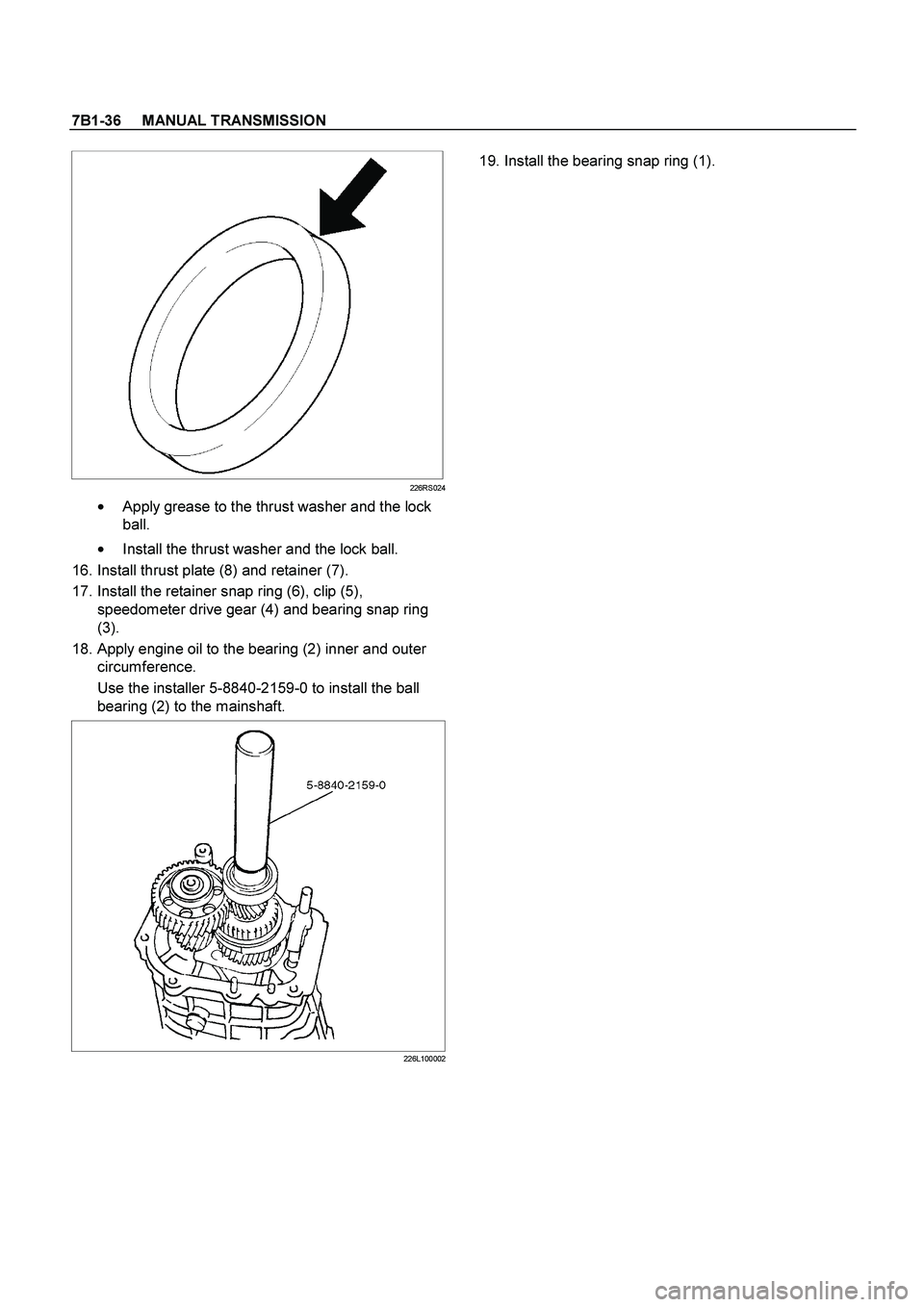
18. Apply engine oil to the bearing (2) inner and outer
circumference.
Use the installer 5-8840-2159-0 to install the ball
bearing (2) to the mainshaft.
226L100002
19. Install the bearing snap ring (1).
Page 3208 of 4264

7B1-44 MANUAL TRANSMISSION
Clutch Hub Spline Play
� Set a dial indicator to the clutch hub to be
measured.
226RS042
�
Move the clutch hub as far as possible to both the
right and the left.
Note the dial indicator reading.
If the measured value exceeds the specified limit,
the clutch hub must be replaced.
Clutch Hub Spline Play
Standard Limit
1st-2nd
3rd-4th 0 - 0.1 mm
(0 - 0.004 in) 0.2 mm
(0.008 in)
Rev. 5th 0 - 0.2 mm
(0 - 0.008 in) 0.3 mm
(0.012 in)
Ball Bearing Play
�
Use a dial indicator to measure the ball bearing play.
Ball Bearing Play
Limit: 0.2 mm (0.008 in)
226RS043
Reassembly
1. Install center roller bearing (29) to counter gear
shaft (30).
�
Apply engine oil to the bearing inner and outer
circumferences.
� Install the roller bearing in the proper direction.
NOTE: Check that outer race moves only in the
direction of arrow.
226RS044
2. Install front roller bearing (28) by performing the
following steps.
� Use bearing installer 5-8840-2194-0 to install the
front roller bearing inner race to the counter gear
shaft (30).
�
Install the outer race and roller assembly.
The snap ring groove must be facing the
transmission front side.
Page 3209 of 4264
 Ring
(2) Outer Race and Roller Assembly
(3) Inner Race
3. Instal")
MANUAL TRANSMISSION 7B1-45
�
Use bearing installer 5-8840-2194-0 to install the
ring.
RTW47BSH000501
Legend
(1) Ring
(2) Outer Race and Roller Assembly
(3) Inner Race
3. Install bearing snap ring (27) to counter gear shaft
(30).
4. Apply engine oil to the needle bearing (25) and the
2nd gear (24) thrust surfaces.
Install the needle bearing (25) and the 2nd gear (24)
to the mainshaft (26).
The 2nd gear (24) dog teeth must be facing the
transmission rear side.
226RS046
5. Assemble 2nd inside ring (23), 2nd outside ring (22),
and 2nd block ring (21) on 2nd gear (24).
�
Apply engine oil to the synchronizer ring friction
surfaces.
226RS047
Legend
(1) Block Ring
(2) Outside Ring
(3) Inside Ring
(4) 2nd Gear
(5) Needle Bearing
6. Assemble 1st-2nd synchronizer assembly (20) by
performing the following steps:
1. Check that the inserts (3) fit snugly into the
clutch hub (5) insert grooves.
2. Check that the inserts springs (4) are fitted to
the inserts as shown in the illustration.
3. Check that the clutch hub (5) and the sleeve (6)
slide smoothly.
Page 3211 of 4264
MANUAL TRANSMISSION 7B1-47
226RS031
9. Install needle bearing (18), 1st block ring (17), 1st
outside ring (16), 1st inside ring (15), and 1st gear
(14).
�
Apply engine oil to the needle bearing, 1st gear
thrust surfaces and synchronizer ring friction
surfaces.
�
The 1st gear dog teeth must be facing the
transmission front side.
226RS053
Legend
(1) 1st Gear
(2) Needle Bearing
(3) Inside Ring
(4) Outside Ring
(5) Block Ring
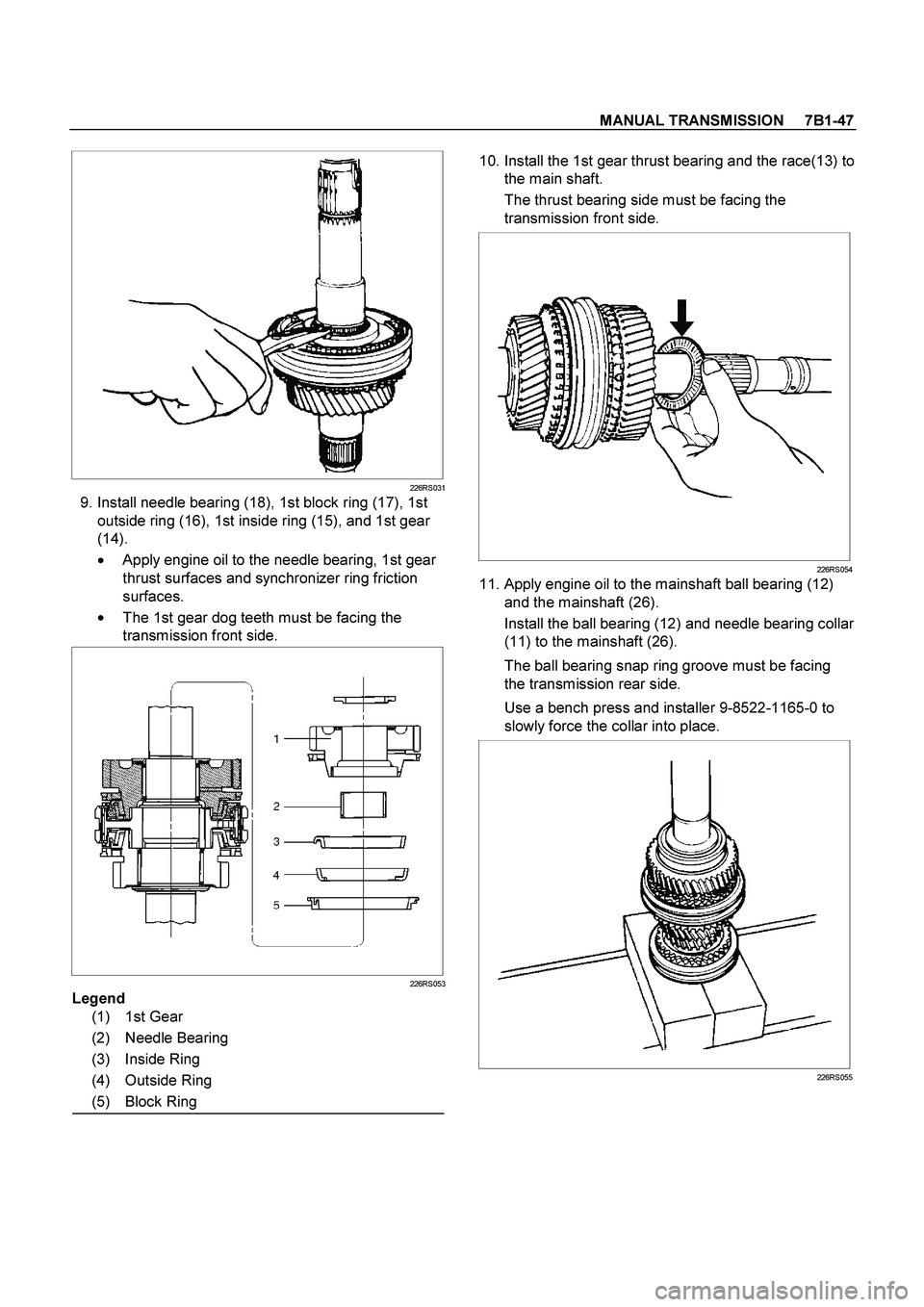
10. Install the 1st gear thrust bearing and the race(13) to
the main shaft.
The thrust bearing side must be facing the
transmission front side.
226RS054
11. Apply engine oil to the mainshaft ball bearing (12)
and the mainshaft (26).
Install the ball bearing (12) and needle bearing collar
(11) to the mainshaft (26).
The ball bearing snap ring groove must be facing
the transmission rear side.
Use a bench press and installer 9-8522-1165-0 to
slowly force the collar into place.
226RS055
Page 3212 of 4264
 and the
3rd gear (9) thrust surfaces.
Install the needle bearing (10) and the 3rd gear (9)
to the mainshaft.
The 3")
7B1-48 MANUAL TRANSMISSION
12. Apply engine oil to the needle bearing (10) and the
3rd gear (9) thrust surfaces.
Install the needle bearing (10) and the 3rd gear (9)
to the mainshaft.
The 3rd gear dog teeth must be facing the
transmission front side.
226RS056
13. Install 3rd block ring (8).
14. Check and install 3rd-4th synchronizer assembly (7)
by the following steps:
1. Check that the inserts (3) fit snugly into the
clutch hub insert grooves.
2. Check that the insert springs (4) are fitted to the
inserts as shown in the illustration.
3. Check that the clutch hub (5) and the sleeve (6)
slide smoothly.
4. Install the synchronizer assembly to the
mainshaft.
The clutch hub face with the heavy boss must be
facing the 3rd gear side.
226RW221
226RS049
15. Select and install mainshaft snap ring(6) in the
following way:
Select the snap ring which will provide the minimum
clearance between the 3rd-4th clutch hub and the
snap ring.
226RS058
There are three snap ring sizes available.
The snap rings are color coded to indicate their
thickness as shown in the figure.
Page 3214 of 4264
7B1-50 MANUAL TRANSMISSION
Main Data and Specifications
General Specifications
MUA 5G MUA 5S
Transmission type Fully synchronized forward and reverse gears
Control method Remote control with the gear shift lever on the floor.
Gear ratio: Transmission 1st 4.008 4.357
2nd 2.301 2.502
3rd 1.427 1.501
4th 1.000 1.000
5th 0.828 0.809
Rev. 3.651 3.970
Transmission oil capacity 2.95 lit. (3.12 US qt)
Type of lubricant Engine oil: Refer to the chart in "SECTION 0"
Page 3219 of 4264
MANUAL TRANSMISSION 7B1-55
2) NOISY OPERATION
Checkpoint Trouble Cause Countermeasure
Replenish or replace the gear
oilInsufficient or improper engine
oil NG
Replace the gear(s)
Replace the gear(s)
Replace the bearing(s)
Gears (Gear whining)Lack of backlash between
meshing gears
Free running gears seizing on
the thrust face or the inner
face
Bearings (Hissing, thumping
or bumping)Worn or broken bearing(s)
Gears (Squealing at high
speeds)
Replace the gear(s)Gears (Growling, humming, or
grinding)Worn, chipped, or cracked
gear(s)
NG NG NG NG OK
OK
OK OK
Gear oil (Metallic rattling)
Page 3220 of 4264
7B1-56 MANUAL TRANSMISSION
2. HARD SHIFTING
Checkpoint Trouble Cause Countermeasure
Change lever play
Clutch pedal free play
Repair or replace the
applicable parts and regrease
Readjust the clutch pedal free
play
Worn change lever sliding
portions
Improper clutch pedal free
play
Change lever operationRepair or regrease the change
lever assembly
Replenish or replace the
engine oil
Hard operating change lever
caused insufficient grease
Insufficient or improper gear
oil
OK
OKNG NG NG NG
OK OKGear oil
Continued on the next page
Shift rod and quadrant box
sliding faces, and other partsReplace the shidt rod and/or
the quadrant boxWorn shift rod and/or sliding
faces
Repair or replace the sleeveSleeve movement failure
NG NG
OKShift block sleeve movement

 NOISY OPERATION
Checkpoint Trouble Cause Countermeasure
Replenish or replace the gear
oilInsufficient or improper engine
oil NG
Replace the gear(s)
Replace")
