Page 3059 of 4264

HEATER AND AIR CONDITIONING 1-49
OIL RETURN OPERATION
There is close affinity between the oil and the refrigerant.
During normal operation, part of the oil recirculates with the
refrigerant in the system.
When checking the amount of oil in the system, or replacing
any component of the system, the compressor must be run in
advance for oil return operation. The procedure is as follows:
1) Open the all doors and engine hood.
2) Start the engine and A/C switch is "ON" and Set the fan
control knob at its highest position.
3) Run the compressor for more than 20 minutes between
800 and 1,000 rpm in order to operate the system.
4) Stop the engine.
REPLACEMENT OF COMPONENT PARTS
When replacing system component parts, supply the following
amount of oil to the component parts to be installed.
Component parts to be installed Amount of oil
Evaporator 50 cm3 (1.7 fl.oz.)
Condenser 30 cm3 (1.0 fl.oz.)
Receiver/drier 30 cm3 (1.0 fl.oz.)
Refrigerant line (One piece) 10 cm3 (0.3 fl.oz.)
Refrigeration oil must be replenished if more than two parts
are removed at the same time. After installing these
components, check compressor oil.
Page 3060 of 4264
1-50 HEATER AND AIR CONDITIONING
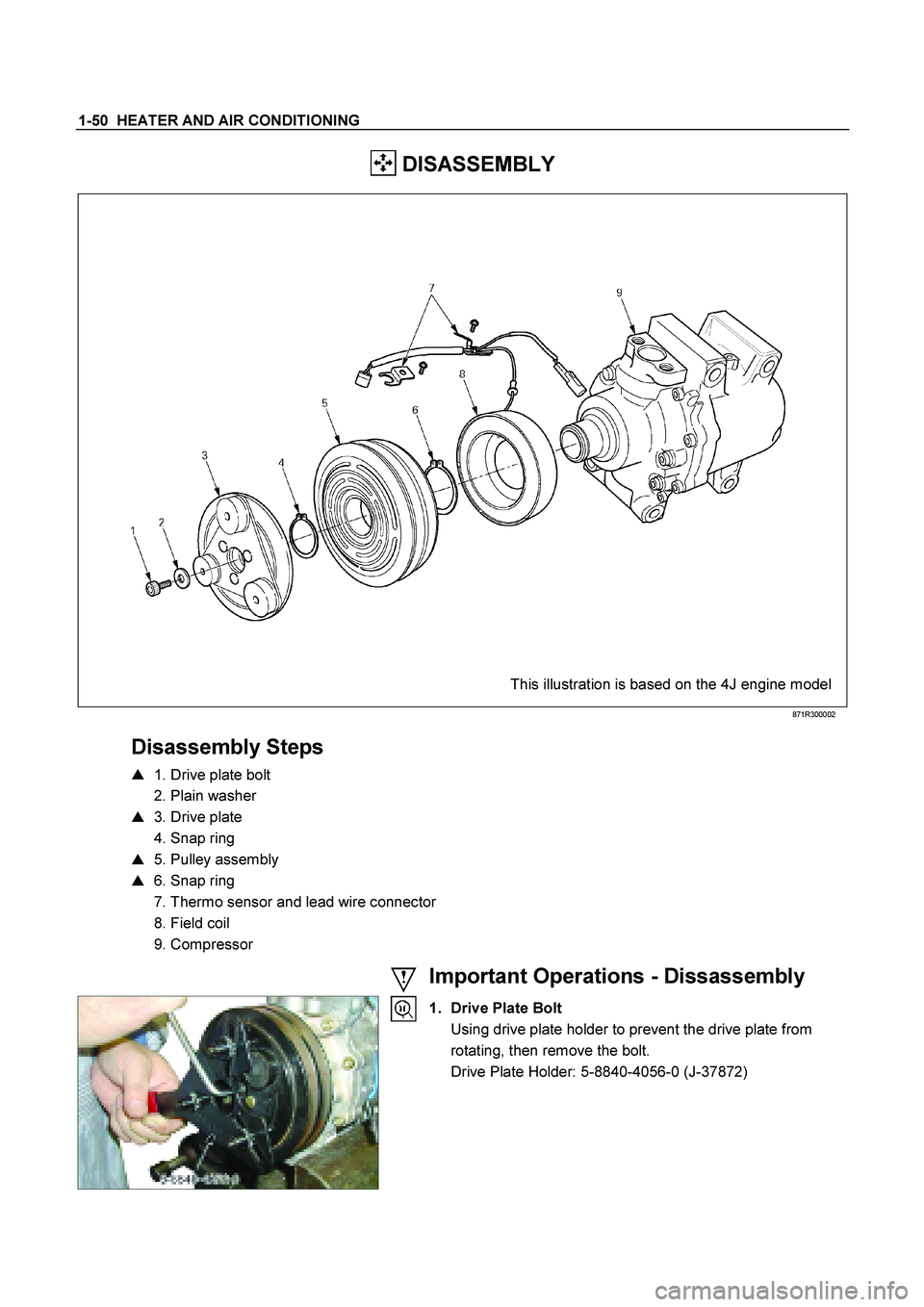
DISASSEMBLY
This illustration is based on the 4J engine model
871R300002
Disassembly Steps
� 1. Drive plate bolt
2. Plain washer
� 3. Drive plate
4. Snap ring
� 5. Pulley assembly
� 6. Snap ring
7. Thermo sensor and lead wire connector
8. Field coil
9. Compressor
Important Operations - Dissassembly
1. Drive Plate Bolt
Using drive plate holder to prevent the drive plate from rotating, then remove the bolt.
Drive Plate Holder: 5-8840-4056-0 (J-37872)
Page 3062 of 4264
1-52 HEATER AND AIR CONDITIONING
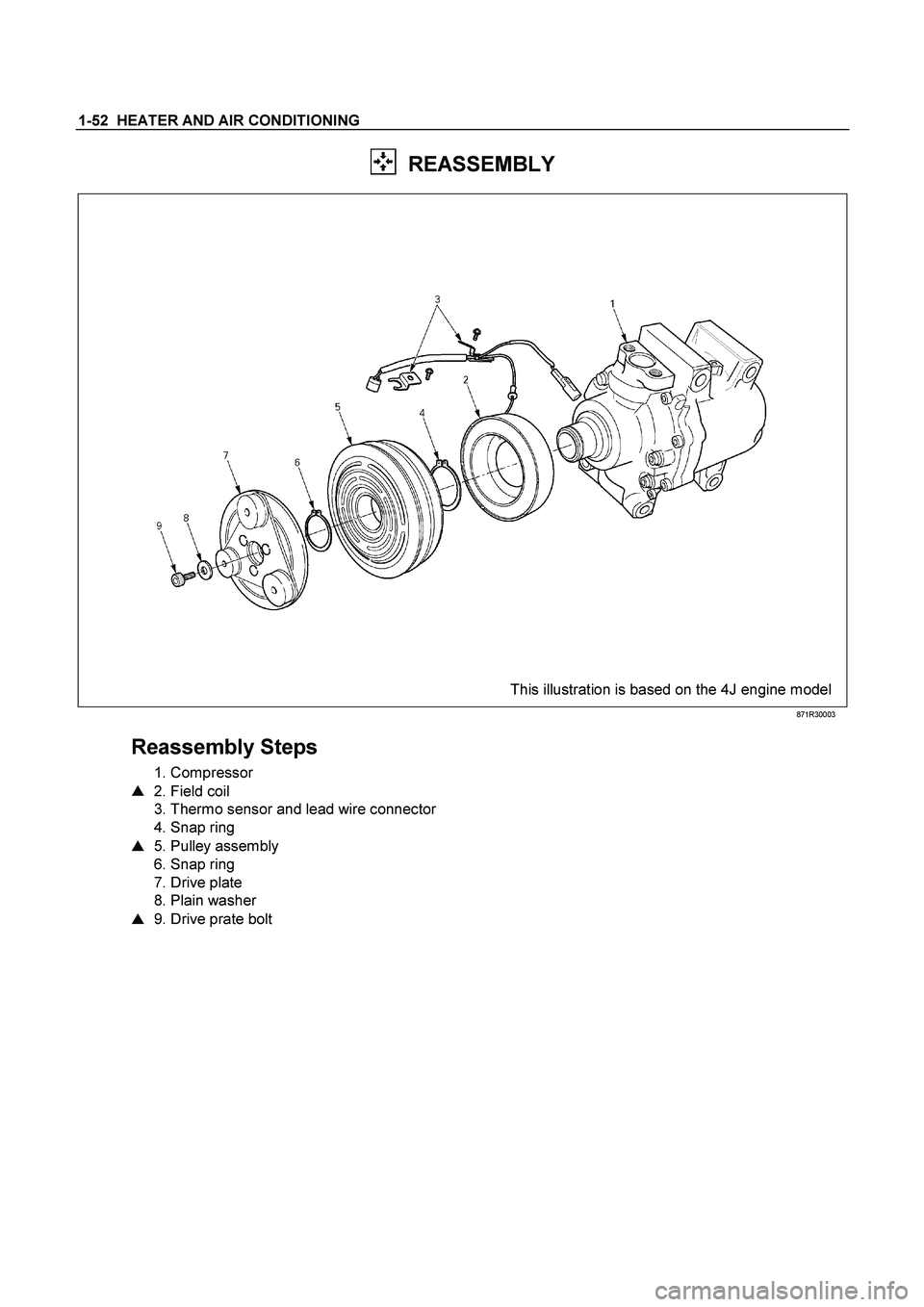
REASSEMBLY
This illustration is based on the 4J engine model
871R30003
Reassembly Steps
1. Compressor
� 2. Field coil
3. Thermo sensor and lead wire connector
4. Snap ring
� 5. Pulley assembly
6. Snap ring
7. Drive plate
8. Plain washer
� 9. Drive prate bolt
Page 3090 of 4264
1-80 HEATER AND AIR CONDITIONING
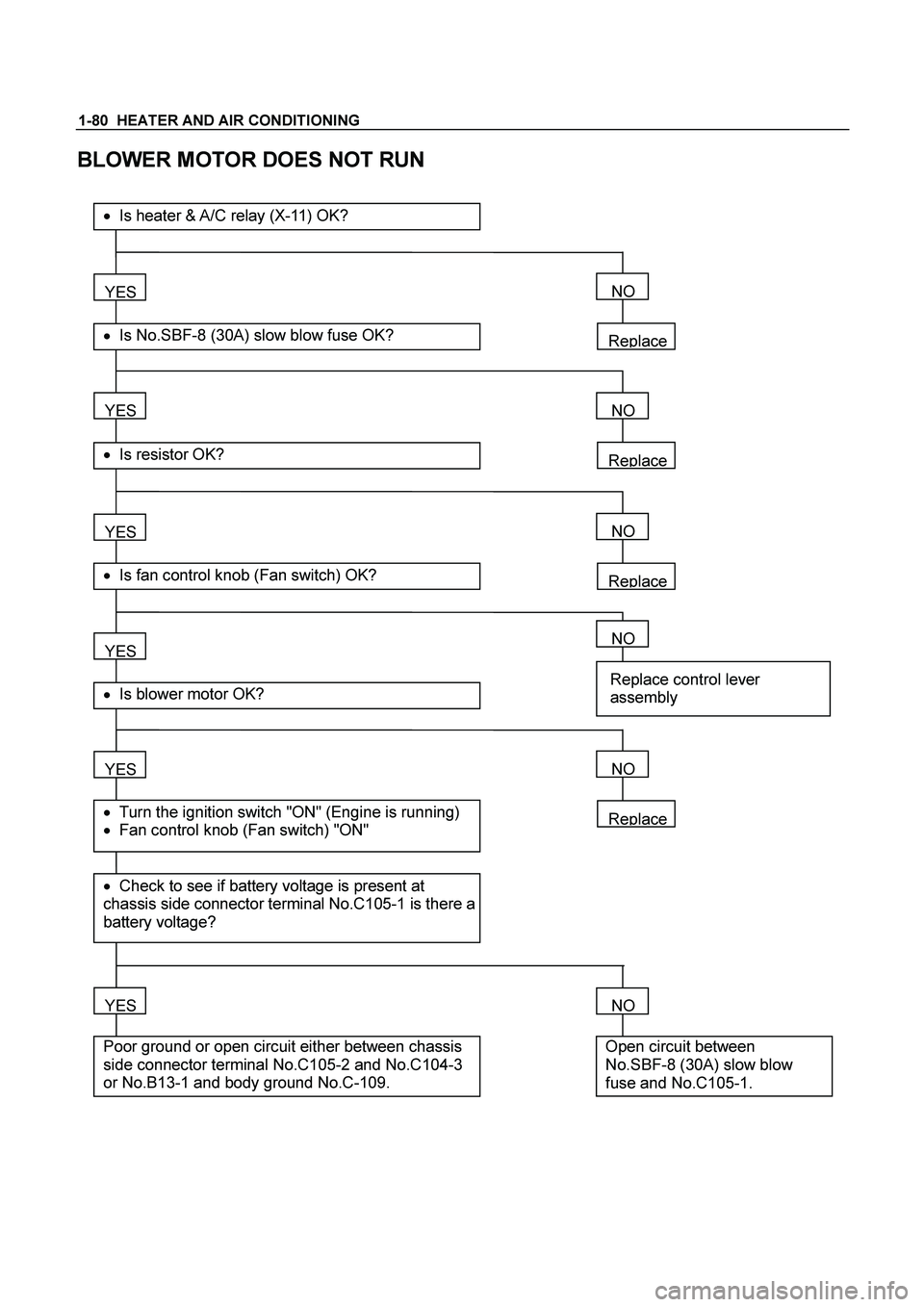
BLOWER MOTOR DOES NOT RUN
Replace
YES
� Is No.SBF-8 (30A) slow blow fuse OK?
��Is heater & A/C relay (X-11) OK?
YES
� Is resistor OK?
YES
� Is fan control knob (Fan switch) OK?
YES
YES
� Check to see if battery voltage is present at
chassis side connector terminal No.C105-1 is there a
battery voltage?
� Turn the ignition switch "ON" (Engine is running)
� Fan control knob (Fan switch) "ON"
� Is blower motor OK?
YES
Poor ground or open circuit either between chassis
side connector terminal No.C105-2 and No.C104-3
or No.B13-1 and body ground No.C-109.
NO
Replace
NO
Replace
NO
NO
Replace control lever
assembly
Replace
NO
NO
Open circuit between
No.SBF-8 (30A) slow blow
fuse and No.C105-1.
Page 3094 of 4264
1-84 HEATER AND AIR CONDITIONING
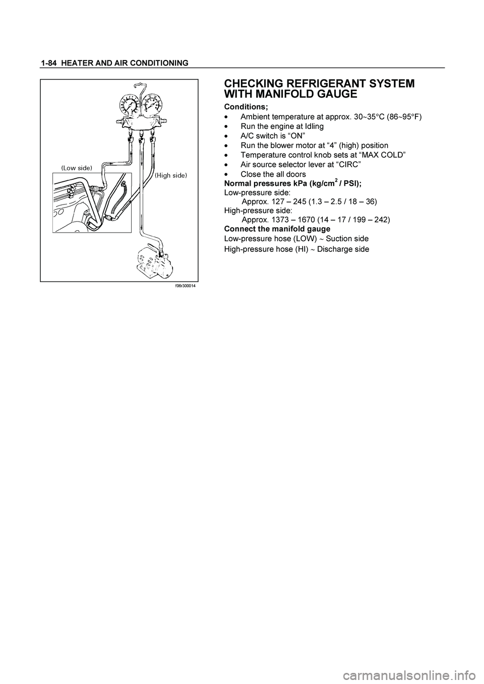
f06r300014
CHECKING REFRIGERANT SYSTEM
WITH MANIFOLD GAUGE
Conditions;
��
Ambient temperature at approx. 30�
35�
C (86�
95�
F)
��
Run the engine at Idling
��A/C switch is “ON”
��
Run the blower motor at “4” (high) position
��
Temperature control knob sets at “MAX COLD”
��
Air source selector lever at “CIRC”
��
Close the all doors
Normal pressures kPa (kg/cm
2 / PSI);
Low-pressure side:
Approx. 127 – 245 (1.3 – 2.5 / 18 – 36)
High-pressure side:
Approx. 1373 – 1670 (14 – 17 / 199 – 242)
Connect the manifold gauge
Low-pressure hose (LOW) � Suction side
High-pressure hose (HI) � Discharge side
Page 3097 of 4264
HEATER AND AIR CONDITIONING 1-87
MAGNETIC CLUTCH
When the A/C switch and the fan control knob (fan switch) are turned on with the engine running, current flows
through the thermostat and the compressor relay to activate the magnetic clutch.
The air conditioning can be stopped by turning off the A/C switch or the fan control knob (fan switch).
However, even when the air conditioning is in operation, the electronic thermostat, the pressure switch or the ECM
is used to stop the air conditioning temporarily by turning off the magnetic clutch in the prearranged conditions to
reduce the engine load which is being caused by the rise in the engine coolant temperature, and the acceleration of
the vehicle, etc.
Page 3100 of 4264
1-90 HEATER AND AIR CONDITIONING
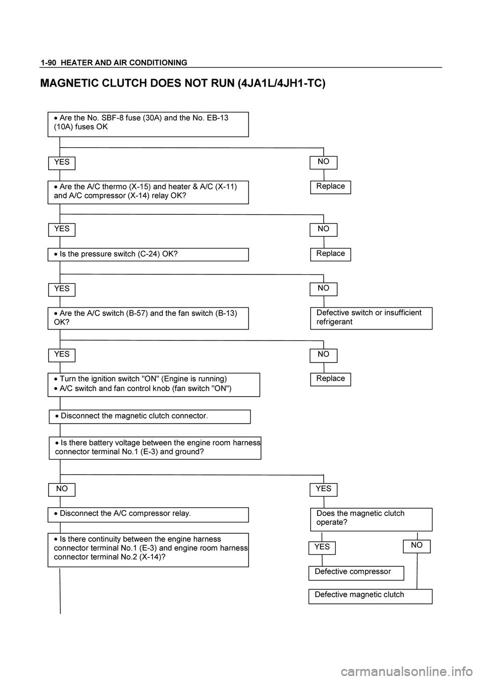
MAGNETIC CLUTCH DOES NOT RUN (4JA1L/4JH1-TC)
Replace
YES
�
Are the A/C thermo (X-15) and heater & A/C (X-11)
and A/C compressor (X-14) relay OK?
� Are the No. SBF-8 fuse (30A) and the No. EB-13
(10A) fuses OK
YES
�
Is the pressure switch (C-24) OK?
YES
�
Are the A/C switch (B-57) and the fan switch (B-13)
OK?
NO
YES
�
Is there continuity between the engine harness
connector terminal No.1 (E-3) and engine room harness
connector terminal No.2 (X-14)?
� Disconnect the A/C compressor relay.
� Turn the ignition switch "ON" (Engine is running)
�
A/C switch and fan control knob (fan switch "ON")
NO
Replace
NO
Defective switch or insufficient
refrigerant
NO
NO
Does the magnetic clutch
operate?
YES
Replace
�
Disconnect the magnetic clutch connector.
� Is there battery voltage between the engine room harness
connector terminal No.1 (E-3) and ground?
Defective compressor
YESNO
Defective magnetic clutch
Page 3101 of 4264

and engine room harness connector
terminal No.2 (X-14).
YES
�
Is there battery v")
HEATER AND AIR CONDITIONING 1-91
Open circuit between the engine
harness connector terminal No.1 (E-3)
and engine room harness connector
terminal No.2 (X-14).
YES
�
Is there battery voltage between the engine room
harness connector terminal No.1 (X-14) and
ground?
YES
�
Disconnect the A/C thermo relay.
YES
�
Is there continuity between the ECM harness
connector terminal No.38 (C-56) and engine
room harness connector terminal No.4 (X-14)?
NO
Open circuit between the No. EB-13
fuse and engine room harness
connector terminal No.1 (X-14).
NO
Open circuit between the engine room
harness connector terminal No.1 (X-
15) and engine room harness
connector terminal No. 3 (X-14).
NO
� Is there continuity between the engine room
harness connector terminal No.3 (X-14) and No.1
(X-15)?
YES
�
Is there continuity between the ECM harness
connector terminal No.30 (C-56) and engine
room harness connector terminal No.2 (X-15)? Open circuit between the engine room
harness connector terminal No.1 (X-
15) and engine room harness
connector terminal No. 3 (X-14).
NO
YES
�
Is there battery voltage between the engine room
harness connector terminal No.4 (X-15) and
ground?
Open circuit between the ECM
harness connector No. 38 (C-56) and
engine room harness connector
terminal No. 4 (X-14).
NO
YES
�
Is there continuity between the engine room
harness connector terminal No. 3 (X-15) and the
engine room harness connector terminal No. 1 (C-
24).
Open circuit between the No. EB-13
fuse and engine room harness
connector terminal No. 4 (X-15).
NO
�
Disconnect the ECM harness connector.
�
Disconnect the pressure switch?
 are turned on with the engine running, current flows
through the thermostat and the comp")