Page 2879 of 4264
ENGINE LUBRICATION 6G-7
Inspection and Repair
CAUTION: Make necessary correction or parts replacement if wear, damage or any other
abnormal conditions are found through
inspection.
Reassembly
To install, follows the disassembly steps in the reverse order.
Important
Sealer - Apply silicon into groove in oil pan lugs prior to fitment of oil pan to block, remove excess sealer after oil pan
is bolted to block.
(2.4L 4 ×4 Model)
4
3
1
2
(2.4L 4 ×2 Model)
4
3
1
2
Torque
Bolts - Tighten bolts to the specified torque.
Torque : 20 N �m (2.0 kgf �m)
Engine oil - Refill engine oil to the oil pan. (Lit)
Replacement Oil Fill Volume 2.4L
Without filter change 4.00
With filter change 4.25
Page 2880 of 4264
6G-8 ENGINE LUBRICATION
MEMO
Page 2881 of 4264
 6H-1
ENGINE
ENGINE SPEED CONTROL SYSTEM (C24SE)
CONTENTS
Service Precaution............................................... 6H-1
Accelerator Pedal Control Ca")
ENGINE SPEED CONTROL SYSTEM (C24SE) 6H-1
ENGINE
ENGINE SPEED CONTROL SYSTEM (C24SE)
CONTENTS
Service Precaution............................................... 6H-1
Accelerator Pedal Control Cable...................... 6H-2
Removal.............................................................. 6H-2
Inspection........................................................... 6H-3
Installation.......................................................... 6H-3
Service Precaution
WARNING: THIS VEHICLE HAS A SUPPLEMENTAL
RESTRAINT SYSTEM (SRS). REFER TO THE SRS
COMPONENT AND WIRING LOCATION VIEW IN
ORDER TO DETERMINE WHETHER YOU ARE
PERFORMING SERVICE ON OR NEAR THE SRS
COMPONENTS OR THE SRS WIRING. WHEN YOU
ARE PERFORMING SERVICE ON OR NEAR THE
SRS COMPONENTS OR THE SRS WIRING, REFE
R
TO THE SRS SERVICE INFORMATION. FAILURE TO
FOLLOW WARNINGS COULD RESULT IN
POSSIBLE AIR BAG DEPLOYMENT, PERSONAL
INJURY, OR OTHERWISE UNNEEDED SRS SYSTEM
REPAIRS.
CAUTION: Always use the correct fastener in the
proper location. When you replace a fastener, use
ONLY the exact part number for that application.
ISUZU will call out those fasteners that require a
replacement after removal. ISUZU will also call out
the fasteners that require thread lockers or thread
sealant. UNLESS OTHERWISE SPECIFIED, do not
use supplemental coatings (Paints, greases, o
r
other corrosion inhibitors) on threaded fasteners o
r
fastener joint interfaces. Generally, such coatings
adversely affect the fastener torque and the joint
clamping force, and may damage the fastener.
When you install fasteners, use the correct
tightening sequence and specifications. Following
these instructions can help you avoid damage to
parts and systems.
Page 2882 of 4264
6H-2 ENGINE SPEED CONTROL SYSTEM (C24SE)
Accelerator Pedal Control Cable
RHD MODEL
RTW46HLF000501
Removal
1. Disconnect the accelerator control cable from the
accelerator pedal and dash panel.
2. Remove the cable clips.
3. Remove the accelerator control cable from
accelerator control cable bracket.
1) Slide the lock in direction A
2) Rotate the ratchet ring in indirection an arro
w
90�.
Page 2883 of 4264
ENGINE SPEED CONTROL SYSTEM (C24SE) 6H-3
4. Remove the accelerator control cable from the
throttle.
LHD MODEL
RTW46AMH000101
Inspection
Check the following items and replace the control
cable if any abnormality is found.
� The control cable should move smoothly.
� The control cable should not be bent or kinked.
� The control cable should not be damage o
r
corrosion.
Installation
1. Install the accelerator control cable to accelerator
control pedal dash panel.
2. Install the accelerator control cable to throttle.
Attach T-END and inner cable to throttle cam o
f
engine.
3. Install accelerator control cable to accelerato
r
bracket.
1) Rotate the ratchet ring in direction an arrow 90�
until both white marking are aligned.
2) Confirm marking of outer cap must be uppe
r
side.
3) Slider the lock in direction B.
4) Confirm ratchet ring is locked.
Page 2884 of 4264
6H-4 ENGINE SPEED CONTROL SYSTEM (C24SE)
MEMO
Page 2933 of 4264

SHEET METAL 2B-1
SECTION 2B
SHEET METAL
This section includes items of front end sheet metal that are attached by bolts, screws or clips and related
accessory components.
Anticorrosion materials have been applied to the interior surfaces of some metal panels to provide rust resistance.
When servicing these panes, areas on which this material has been disturbed, should be properly recoated with
service-type anticorrosion material.
TABLE OF CONTENTS
PAGE
Engine Hood Assembly ..................................................................................................... 2B- 2
Engine Hood Lock ............................................................................................................. 2B- 5
Front Fender Panel ............................................................................................................ 2B- 7
Radiator Grille .................................................................................................................... 2B- 10
Rear Body ........................................................................................................................... 2B- 11
Body Mounting ................................................................................................................... 2B- 13
Body Dimension.................................................................................................................2B- 19
Page 2934 of 4264
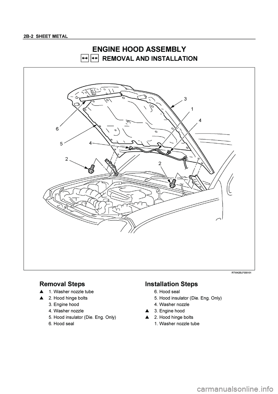
2B-2 SHEET METAL
ENGINE HOOD ASSEMBLY
REMOVAL AND INSTALLATION
RTW42BLF000101
Removal Steps
Installation Steps
�
1. Washer nozzle tube
6. Hood seal
�
2. Hood hinge bolts
5. Hood insulator (Die. Eng. Only)
3. Engine hood
4. Washer nozzle
4. Washer nozzle
�
3. Engine hood
5. Hood insulator (Die. Eng. Only)
�
2. Hood hinge bolts
6. Hood seal
1. Washer nozzle tube


Accelerator Pedal Control Cable
RHD MODEL
RTW46HLF000501
Removal
1. Disconnect the accelerator control cable from the
accelerator pedal and das")
 6H-3
4. Remove the accelerator control cable from the
throttle.
LHD MODEL
RTW46AMH000101
Inspection
Check the following items and replace the cont")

MEMO")