Page 3241 of 4264

MANUAL TRANSMISSION 7B1-77
Disassembly
1. Clean the exterior of the unit with solvent.
2. Remove the drain plug from the transmission case
and drain the lubricant.
3. Remove the clutch release bearing with spring (5)
from the transmission case.
4. Remove the shift fork, and boot. (Diesel engine,
C24NE)
5. Remove the shift fork snap pin. (6VE1)
6. Remove the shift fork pin and shift fork from the
fulcrum bridge. (6VE1)
RTW47BSH000601
Legend
(1) Shift fork pin
(2) Shift fork
(3) Release bearing
7. Remove the fulcrum bridge from the transmission
case. (6VE1)
RTW37ASH0002
Legend
(1) Fulcrum bridge
8. Remove the front cover (8) and gasket from the
transmission case.
9. Remove snap ring (7) fixing counter front bearing.
10. Use a pair of snap ring pliers to remove the snap
ring (9) fixing top gear bearing.
226RS001
11. Remove gear control box assembly (1).
12. Remove the rear case assembly (2) from the
transmission case (4) and intermediate plate (3).
13. Remove intermediate plate with gear assembly (3)
from transmission case (4).
Page 3242 of 4264
 Installer 5-8840-2797-0
(2) Grip 5-8840-0007-0
1. Remove the oil seal from the rear case and discard
the used")
7B1-78 MANUAL TRANSMISSION
Rear Oil Seal Replacement
220R300025
Legend
(1) Installer 5-8840-2797-0
(2) Grip 5-8840-0007-0
1. Remove the oil seal from the rear case and discard
the used oil seal.
2. Apply engine oil to new oil seal outer surfaces.
3. Apply recommended grease (BESCO L2) or
equivalent to the oil seal lip.
4. Use the oil seal installer 5-8840-2797-0 and grip 5-
8840-0007-0 to install the oil seal to the rear case.
Reassembly
1. Apply recommended liquid gasket (LOCTITE 17430)
or its equivalent to the transmission case (4),
intermediate plate (3) and rear case (2) fitting
surfaces.
2. Install the intermediate plate with gear assembly (3)
to the transmission case (4).
Pull out the top gear shaft until the ball bearing snap
ring groove protrudes from the transmission case
front cover fitting face.
Avoid subjecting the mainshaft to sudden shock or
stress.
3. Install the rear case with oil seal (2) on the
intermediate plate with gear (3) by performing the
following steps.
�
Cover the shaft splines with adhesive tape.
This will prevent damage to the oil seal lip.
�
Tighten the transmission rear case bolts and
nuts to the specified torque.
Torque: 37 N�
�� �m (3.8 kg�
�� �m/27 lb�
�� �ft)
220R300026
Notes When Tightening the Bolt:
�
After cleaning the bolt hole, dry it thoroughly with air.
� After cleaning the screw face of a removed bolt or
new one, dry it thoroughly. Apply recommended
liquid gasket (LOCTITE 242) or its equivalent on
them before tightening it.
4. Install a new gasket and gear control box assembly
(1).
Install the harness clips and brackets and then
tighten four new gear control box bolts to the
specified torque.
Torque: 20 N�
�� �m (2.0 kg�
�� �m/14 lb�
�� �ft)
261R300004
Page 3243 of 4264
 and counter
front bearing snap ring (7).
�
Use a pair of snap ring pliers to install the snap
rings to the mainshaft a")
MANUAL TRANSMISSION 7B1-79
5. Install top gear bearing snap ring (9) and counter
front bearing snap ring (7).
�
Use a pair of snap ring pliers to install the snap
rings to the mainshaft and countershaft.
�
The snap rings must be fully inserted into the
bearing snap ring groove.
6. Front cover with oil seal (8).
Front Cover Oil Seal Replacement
�
Remove the oil seal from the front cover.
�
Apply engine oil to a new oil seal outer
circumference.
� Apply recommended grease to the oil seal lip.
�
Use the oil seal installer 5-8840-0026-0 to install
the oil seal to the front cover.
220R3000020
8. Apply molybdenum disulfide type grease to the
areas as shown in the figure and install shift fork (6).
(Diesel engine, C24NE)
F07L100026
9. Install the fulcrum bridge to the transmission case.
(6VE1)
Torque: 38 N�
�� �m (3.9 kg�
�� �m/28 lb�
�� �ft)
RTW37ASH0002
Legend
(1) Fulcrum bridge
10. Apply molybdenum disulfide type grease to the pin
hole inner circumferences and thrust surfaces.
(6VE1)
11. Attach the shift fork to the fulcrum bridge and insert
the pin from below of the fulcrum bridge. (6VE1)
Page 3254 of 4264
7B1-90 MANUAL TRANSMISSION
6. Mesh the 1st-2nd and 3rd-4th synchronizers with
both the 1st and 3rd gears (double engagement).
226RS015
This will prevent the mainshaft from turning.
7. Install the new mainshaft hub nut.
Use the mainshaft nut wrench 5-8840-2156-0 to
tighten the mainshaft nut (20) to the specified
torque.
Torque: 137 N�
�� �m (14 kg�
�� �m/101 lb�
�� �ft)
226RW214
8. Use a punch to stake the mainshaft nut (20).
226RW153
9. Install needle bearing (19), 5th block ring (18), and
5th gear (17).
10. Apply engine oil to the counter reverse gear (16) and
the reverse gear (23).
Install the counter reverse gear (16) to the counter
shaft.
The reverse gear projection must be facing the
intermediate plate.
226RW151
Page 3257 of 4264
MANUAL TRANSMISSION 7B1-93
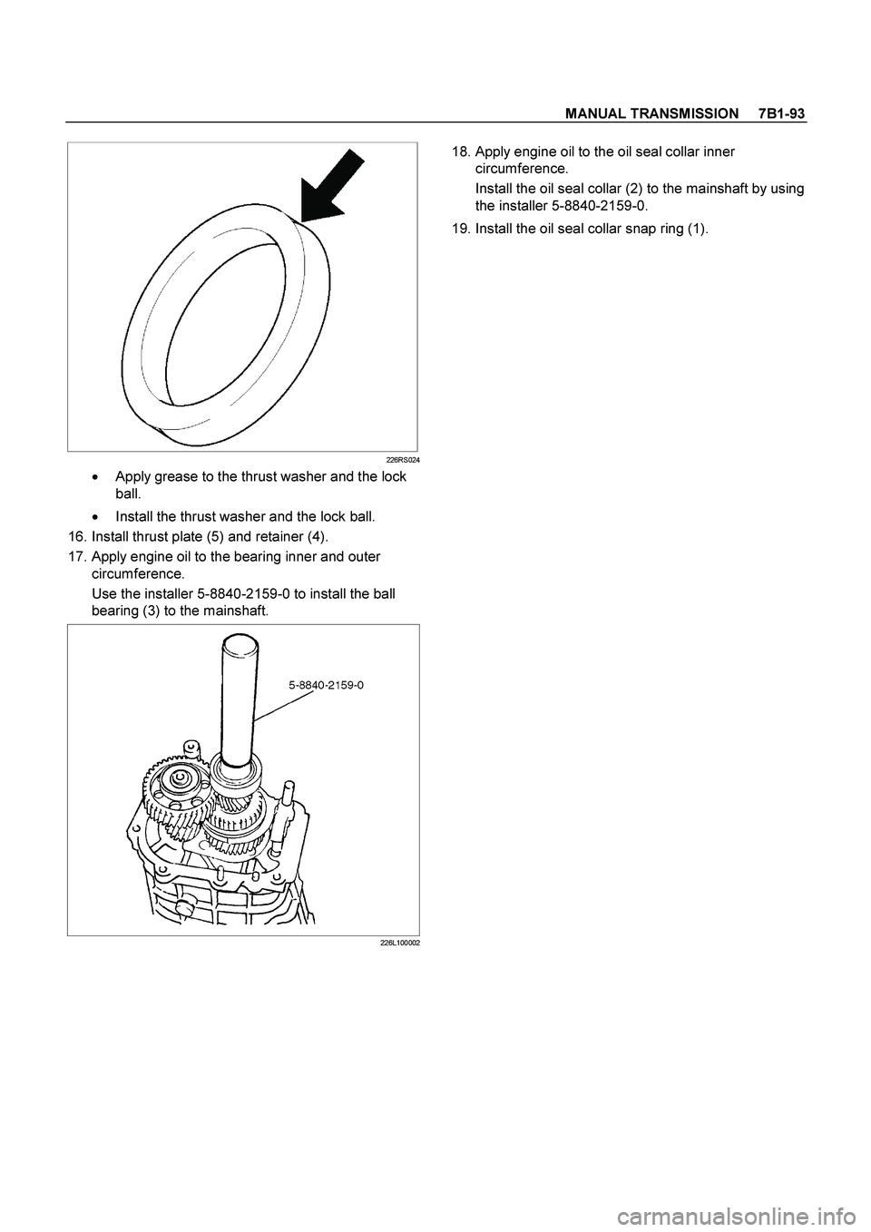
226RS024
�
Apply grease to the thrust washer and the lock
ball.
�
Install the thrust washer and the lock ball.
16. Install thrust plate (5) and retainer (4).
17. Apply engine oil to the bearing inner and outer
circumference.
Use the installer 5-8840-2159-0 to install the ball
bearing (3) to the mainshaft.
226L100002
18. Apply engine oil to the oil seal collar inner
circumference.
Install the oil seal collar (2) to the mainshaft by using
the installer 5-8840-2159-0.
19. Install the oil seal collar snap ring (1).
Page 3265 of 4264

MANUAL TRANSMISSION 7B1-101
Clutch Hub Spline Play
� Set a dial indicator to the clutch hub to be
measured.
226RS042
�
Move the clutch hub as far as possible to both the
right and the left.
Note the dial indicator reading.
If the measured value exceeds the specified limit,
the clutch hub must be replaced.
Clutch Hub Spline Play
Standard Limit
1st-2nd
3rd-4th 0 - 0.1 mm
(0 - 0.004 in) 0.2 mm
(0.008 in)
Rev. 5th 0 - 0.2 mm
(0 - 0.008 in) 0.3 mm
(0.012 in)
Ball Bearing Play
�
Use a dial indicator to measure the ball bearing play.
Ball Bearing Play
Limit: 0.2 mm (0.008 in)
226RS043
Reassembly
1. Install center roller bearing (29) to counter gear
shaft (30).
�
Apply engine oil to the bearing inner and outer
circumferences.
�
Install the roller bearing in the proper direction.
NOTE: Check that outer race moves only in the
direction of arrow.
226RS044
2. Install front roller bearing (28) by performing the
following steps.
�
Use bearing installer 5-8840-2194-0 to install the
front roller bearing inner race to the counter gear
shaft (30).
�
Install the outer race and roller assembly.
The snap ring groove must be facing the
transmission front side.
Page 3266 of 4264
 Ring
(2) Outer Race and Roller Assembly
(3) Inner Race
3. Install")
7B1-102 MANUAL TRANSMISSION
�
Use bearing installer 5-8840-2194-0 to install the
ring.
226RS045
Legend
(1) Ring
(2) Outer Race and Roller Assembly
(3) Inner Race
3. Install bearing snap ring (27) to counter gear shaft
(30).
4. Apply engine oil to the needle bearing (25) and the
2nd gear (24) thrust surfaces.
Install the needle bearing (25) and the 2nd gear (24)
to the mainshaft (26).
The 2nd gear (24) dog teeth must be facing the
transmission rear side.
226RS046
5. Assemble 2nd inside ring (23), 2nd outside ring (22),
and 2nd block ring (21).
�
Apply engine oil to the synchronizer ring friction
surfaces.
226RS047
Legend
(1) Block Ring
(2) Outside Ring
(3) Inside Ring
(4) 2nd Gear
(5) Needle Bearing
6. Assemble 1st-2nd synchronizer assembly (20) by
performing the following steps:
1. Check that the inserts (3) fit snugly into the
clutch hub (5) insert grooves.
2. Check that the inserts springs (4) are fitted to
the inserts as shown in the illustration.
3. Check that the clutch hub (5) and the sleeve (6)
slide smoothly.
Page 3268 of 4264
7B1-104 MANUAL TRANSMISSION
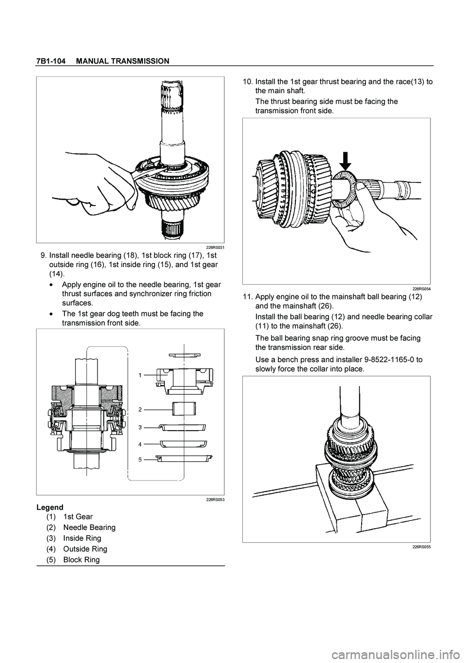
226RS031
9. Install needle bearing (18), 1st block ring (17), 1st
outside ring (16), 1st inside ring (15), and 1st gear
(14).
�
Apply engine oil to the needle bearing, 1st gear
thrust surfaces and synchronizer ring friction
surfaces.
�
The 1st gear dog teeth must be facing the
transmission front side.
226RS053
Legend
(1) 1st Gear
(2) Needle Bearing
(3) Inside Ring
(4) Outside Ring
(5) Block Ring
10. Install the 1st gear thrust bearing and the race(13) to
the main shaft.
The thrust bearing side must be facing the
transmission front side.
226RS054
11. Apply engine oil to the mainshaft ball bearing (12)
and the mainshaft (26).
Install the ball bearing (12) and needle bearing collar
(11) to the mainshaft (26).
The ball bearing snap ring groove must be facing
the transmission rear side.
Use a bench press and installer 9-8522-1165-0 to
slowly force the collar into place.
226RS055
.
226RS015
This will prevent the mainshaft from turning.
7.")