Page 1850 of 4264

Exhaust Manifold LH
Removal
1. Disconnect battery ground cable.
2. Disconnect O
2 sensor connector.
3. Remove torsion bar. Refer to removal procedure in
Front")
6A-26 ENGINE MECHANICAL (6VE1 3.5L)
Exhaust Manifold LH
Removal
1. Disconnect battery ground cable.
2. Disconnect O
2 sensor connector.
3. Remove torsion bar. Refer to removal procedure in
Front Suspension section.
4. Remove exhaust front pipe three stud nuts from
exhaust side and two nuts from rear end o
f
exhaust front pipe.
RTW36FSH000201
5. Remove heat protector two fixing bolts then the
heat protector.
6. Remove a bolt on engine LH side for ai
r
conditioner (A/C) compressor bracket and loosen
two bolts for A/C compressor then move A/C
compressor to front side.
7. Remove exhaust manifold eight fixing nuts and
remove exhaust manifold from the engine.
Installation
1. Install exhaust manifold and tighten exhaust
manifold fixing nuts to the specified torque with
new nuts.
Torque: 52 N�
�� �m (5.3 kg�
�� �m/38 lb ft)
2. Install heat protector.
3. Install exhaust front pipe and tighten three stud
nuts and two nuts to the specified torque.
Torque:
Stud nuts: 67 N�
�� �m (6.8 kg�
�� �m/49 lb ft)
Nuts: 43 N�
�� �m (4.4 kg�
�� �m/32 lb ft)
RTW36FSH000201
4. Install the torsion bar and readjust the vehicle
height. Refer to installation and vehicle heigh
t
adjustment procedure for front suspension.
5. Set A/C compressor to normal position and tighten
two bolts and a bolt to the specified torque.
Torque : 40 N�
�� �m (4.1 kg�
�� �m/30 lb ft)
6. Reconnect O
2 sensor connector.
7. Install air cleaner duct assembly.
Page 1851 of 4264
ENGINE MECHANICAL (6VE1 3.5L) 6A-27
Exhaust Manifold RH
Removal
1. Disconnect battery ground cable.
2. Remove exhaust front pipe three stud nuts and
two nuts then disconnect exhaust front pipe.
RTW36FSH000101
3. Remove steering shaft. Refer to removal
procedure in Steering section.
4. Remove heat protector two fixing bolts then the
heat protector.
5. Remove EGR pipe.
6. Remove exhaust manifold eight fixing nuts then
the exhaust manifold.
Installation
1. Install exhaust manifold and tighten bolts to the
specified torque.
Torque: 52 N�
�� �m (5.3 kg�
�� �m/38 lb ft)
2. Install EGR pipe.
Torque: 29 N�
�� �m (3.0 kg�
�� �m/22 lb ft)
3. Install heat protector
4. Install exhaust front pipe and tighten three stud
nuts and two nuts to the specified torque.
Torque:
Stud nuts: 67 N�
�� �m (6.8 kg�
�� �m/49 lb ft)
Nuts: 43 N�
�� �m (4.4 kg�
�� �m/32 lb ft)
5. Install steering shaft. Refer to installation
procedure in Steering section.
Page 1852 of 4264

Crankshaft Pulley
Removal
1. Disconnect battery ground cable.
2. Remove air cleaner assembly.
3. Remove radiator upper fan shroud from radiator.
4. Move serp")
6A-28 ENGINE MECHANICAL (6VE1 3.5L)
Crankshaft Pulley
Removal
1. Disconnect battery ground cable.
2. Remove air cleaner assembly.
3. Remove radiator upper fan shroud from radiator.
4. Move serpentine belt tensioner to loose side using
wrench then remove serpentine belt.
850RW001
Legend
(1) Crankshaft Pulley
(2) Cooling Fan Pulley
(3) Tensioner
(4) Generator
(5) Air Conditioner Compressor
(6) Power Steering Oil Pump
(7) Serpentine Belt
5. Remove cooling fan assembly four fixing nuts,
then the cooling fan assembly.
6. Remove crankshaft pulley assembly using
5�8840�0133�0 crankshaft holder, hold crankshaf
t
pulley then remove center bolt and pulley.
Installation
1. Install crankshaft pulley using 5�8840�0133�0
crankshaft holder, hold the crankshaft pulley and
tighten center bolt to the specified torque.
Torque: 167 N�
�� �m (17.0 kg�
�� �m/123 lb ft)
2. Install cooling fan assembly and tighten bolts/nuts
to the specified torque.
Torque: 25 N�
�� �m (2.5 kg�
�� �m/18 lb ft) for fan pulley
and fan bracket.
Torque: 10 N�
�� �m (1.0 kg�
�� �m/88.5 lb in) for fan and
clutch assembly.
3. Move serpentine belt tensioner to loose side using
wrench, then install serpentine belt to normal
position.
4. Install radiator upper fan shroud.
5. Install air cleaner assembly.
Page 1853 of 4264
 6A-29
Timing Belt
Removal
1. Disconnect battery ground cable.
2. Remove air cleaner assembly.
3. Remove radiator upper fan shroud from radiator.
4. Move drive belt")
ENGINE MECHANICAL (6VE1 3.5L) 6A-29
Timing Belt
Removal
1. Disconnect battery ground cable.
2. Remove air cleaner assembly.
3. Remove radiator upper fan shroud from radiator.
4. Move drive belt tensioner to loose side using
wrench then remove drive belt.
850RW001
Legend
(1) Crankshaft Pulley
(2) Cooling Fan Pulley
(3) Tensioner
(4) Generator
(5) Air Conditioner Compressor
(6) Power Steering Oil Pump
(7) Drive Belt
5. Remove cooling fan assembly four nuts, then the
cooling fan assembly.
6. Remove cooling fan drive pulley assembly.
7. Remove idle pulley assembly.
8. Remove serpentine belt tensioner assembly.
9. Remove power steering pump assembly.
10. Remove crankshaft pulley assembly using
5�8840�0133�0 crankshaft holder, hold crankshaf
t
pulley remove center bolt, then the pulley.
11. Remove right side timing belt cover then left side
timing belt cover.
12. Remove lower timing belt cover 13. Remove pusher.
CAUTION: The pusher prevents air from entering
the oil chamber. Its rod must always be facing
upward.
014RW011
Legend
(1) Up Side
(2) Down Side
(3) Direction For Installation
(4) Locking Pin
14. Remove timing belt.
CAUTION:
1. Do not bend or twist the belt, otherwise its
core could be damaged. The belt should not be
bent at a radius less than 30 mm.
2. Do not allow oil or other chemical substances
to come in contact with the belt. They will
shorten the life.
3. Do not attempt to pry or stretch the belt with a
screw driver or any other tool during
installation.
4. Store timing belt in a cool and dark place.
Never expose the belt direct sunlight or heat.
Page 1856 of 4264
6A-32 ENGINE MECHANICAL (6VE1 3.5L)
2. Install pusher and tighten bolt to the specified
torque.
Torque: 25 N�
�� �m (2.5 Kg�
�� �m/18 lb ft)
1. Install the pusher while pushing the tension
pulley to the belt.
2. Pull out pin from the pusher.
NOTE: When reusing the pusher, press the pusher with
approximately 100Kg to retract the rod, and insert a pin
(1.4 mm piano wire).
014RW011
Legend
(1) Up Side
(2) Down Side
(3) Direction for Installation
(4) Locking Pin
3. Remove double clips or equivalent clips, from
timing belt pulleys.
Turn the crankshaft pulley clockwise by two
turns.
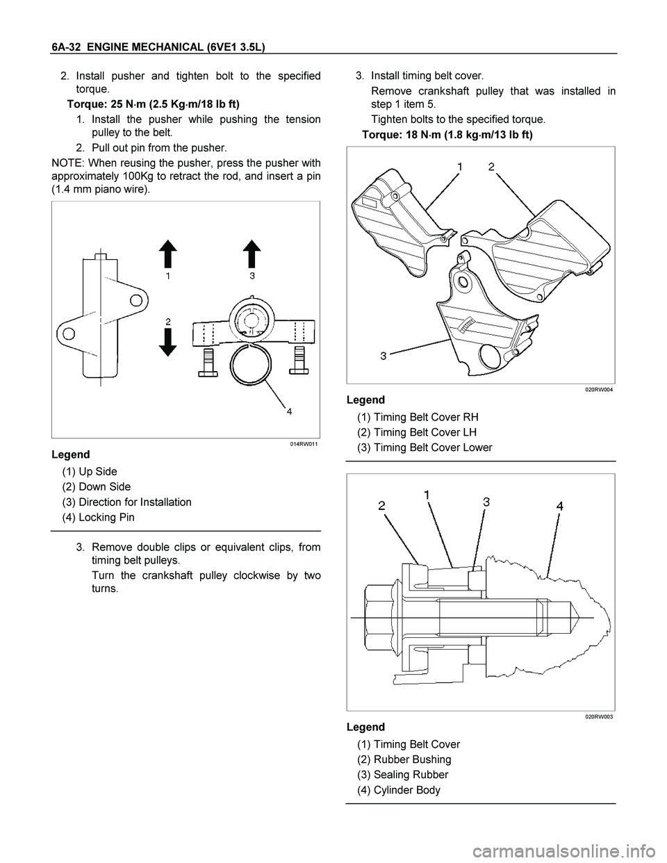
3. Install timing belt cover.
Remove crankshaft pulley that was installed in
step 1 item 5.
Tighten bolts to the specified torque.
Torque: 18 N�
�� �m (1.8 kg�
�� �m/13 lb ft)
020RW004
Legend
(1) Timing Belt Cover RH
(2) Timing Belt Cover LH
(3) Timing Belt Cover Lower
020RW003
Legend
(1) Timing Belt Cover
(2) Rubber Bushing
(3) Sealing Rubber
(4) Cylinder Body
Page 1858 of 4264

Camshaft
Removal
1. Disconnect battery ground cable.
2. Remove crankshaft pulley.
� Refer to removal procedure for Crankshaf
t
Pulley in this manual.
3. Remo")
6A-34 ENGINE MECHANICAL (6VE1 3.5L)
Camshaft
Removal
1. Disconnect battery ground cable.
2. Remove crankshaft pulley.
� Refer to removal procedure for Crankshaf
t
Pulley in this manual.
3. Remove timing belt.
� Refer to removal procedure for Timing Belt in
this manual.
4. Remove cylinder head cover LH.
� Refer to removal procedure for Cylinder Head
Cover LH in this manual.
5. Remove cylinder head cover RH.
� Refer to removal procedure for Cylinder Head
Cover RH in this manual.
6. Remove twenty fixing bolts from inlet and exhaus
t
camshaft bracket on one side bank, then camshaft
brackets.
014RW027
7. Remove camshaft assembly.
8. Remove fixing bolt for camshaft drive gear pulley.
9. Remove three fixing bolts from camshaft drive
gear retainer, then camshaft drive gear assembly.
014RW026
Legend
(1) Right Bank
(2) Left Bank
(3) Timing Mark on Retainer
Installation
1. Install camshaft drive gear assembly and tighten
three bolts to the specified torque.
Torque: 10 N�
�� �m (1.0 kg�
�� �m/7 lb ft)
2. Tighten bolt for camshaft drive gear assembly
pulley to the specified torque.
Torque: 98 N�
�� �m (10.0 kg�
�� �m/72 lb ft)
3. Tighten sub gear setting bolt.
1. Use 5�8840�2443�0 to turn sub gear to righ
t
direction until it aligns with the M5 bolt hole
between camshaft driven gear and sub gear.
2. Tighten the M5 bolt to a suitable torque to
prevent the sub gear from moving.
Page 1861 of 4264
 6A-37
Cylinder Head
Removal
1. Remove engine hood.
2. Disconnect battery ground cable.
3. Drain radiator coolant.
4. Drain engine oil.
5. Remove crankshaft pulley")
ENGINE MECHANICAL (6VE1 3.5L) 6A-37
Cylinder Head
Removal
1. Remove engine hood.
2. Disconnect battery ground cable.
3. Drain radiator coolant.
4. Drain engine oil.
5. Remove crankshaft pulley.
� Refer to removal procedure for Crankshaf
t
Pulley in this manual.
6. Remove timing belt.
� Refer to removal procedure for Timing Belt in
this manual.
7. Remove cylinder head cover LH.
� Refer to removal procedure for Cylinder Head
Cover LH in this manual.
8. Remove cylinder head cover RH.
� Refer to removal procedure for Cylinder Head
Cover RH in this manual.
9. Remove common chamber.
� Refer to removal procedure for Common
Chamber in this manual.
10. Remove cylinder head assembly.
1. Loosen eights bolts for tight cylinder head.
2. Remove cylinder head assembly.
014RW028
Legend
(1) Cylinder Head
(2) Cylinder Head Bolt
(3) Camshaft
Installation
1. Install cylinder head assembly to cylinder block.
1. Put cylinder head gasket on the cylinder block.
NOTE: There is discrimination mark “R" for righ
t
bank and “L" for left bank on the cylinder head
gasket as shown in the illustration.
Do not reuse cylinder head gasket.
011RW005
2. Align dowel pin hole to dowel pin on the
cylinder block.
3. Tighten two bolts temporarily by hand to
prevent the cylinder head assembly from
moving.
4. Using 9�8511�4209�0 cylinder head bol
t
wrench, tighten bolts in numerical order as
shown in the illustration to the specified torque.
Page 1863 of 4264
 6A-39
Valve Stem Oil Controller, Valve Spring and Valve Guide
Removal
1. Disconnect battery ground cable.
� Drain engine oil.
2. Drain engine coolant.
3. Remove cy")
ENGINE MECHANICAL (6VE1 3.5L) 6A-39
Valve Stem Oil Controller, Valve Spring and Valve Guide
Removal
1. Disconnect battery ground cable.
� Drain engine oil.
2. Drain engine coolant.
3. Remove cylinder head assembly.
� Refer to removal procedure for Cylinder Head
in this manual.
4. Remove camshaft.
� Refer to removal procedure for Camshaft in this
manual.
5. Remove tappets with shim.
NOTE: Do not damage shim surface.
6. Remove valve springs using 5�8840�2446�0
valve spring compressor and 5�8840�2547�0
valve spring compressor adapter then remove
upper valve spring seat and lower seat.
014RW042
7. Remove oil controller using 5�8840�0623�0 oil
controller remover, remove each valve stem oil
controller.
8. Remove valve guide using 5�8840�2549�0 valve
guide replacer.
Installation
1. Install valve guide using 5�8840�2442�0 valve
guide installer.
2. Install oil controller using 5�8840�0624�0 oil
controller installer.
3. Install lower valve spring seat, valve spring and
upper valve spring seat then put split collars on the
upper spring seat, using 5�8840�2442�0 valve
spring compressor and 5�8840�0624�0 valve
spring compressor adapter to install the spli
t
collars.
014RW042
4. Install tappet with shim.
5. Install camshaft assembly.
� Refer to installation procedure for Camshaft in
this manual.
6. Install cylinder head assembly.
� Refer to installation procedure for Cylinde
r
Head in this manual.
7. Fill engine oil until full level.
8. Fill engine coolant.
 6A-27
Exhaust Manifold RH
Removal
1. Disconnect battery ground cable.
2. Remove exhaust front pipe three stud nuts and
two nuts then disconnect exhaust front pipe.")