Page 661 of 4264

ELECTRICAL-BODY AND CHASSIS 8A-3
PAGE
Power Window ........................................................................................................... 8A- 310
Audio, Clock and Cigarette Lighter .......................................................................... 8A- 329
Power Door Mirror ...................................................................................................... 8A- 337
Rear Defogger ............................................................................................................ 8A- 349
SRS-Air Bag ................................................................................................................ 8A- 358
Transfer Case Control Module .................................................................................. 8A- 361
Anti-Lock Brake System ............................................................................................ 8A- 373
Immobilizer ................................................................................................................. 8A- 376
Keyless Entry ............................................................................................................. 8A- 385
Anti Theft ....................................................................................................................8A- 400
Auto Cruise ................................................................................................................. 8A- 412
Trailer Hitch ................................................................................................................ 8A- 415
Connector List ................................................................................................................8A- 418
Page 995 of 4264
ELECTRICAL-BODY AND CHASSIS 8A-337
POWER DOOR MIRROR
PARTS LOCATION (RHD)
RTW48AXF020401 & RTW48AXF020501
Page 999 of 4264
ELECTRICAL-BODY AND CHASSIS 8A-341
TROUBLESHOOTING
QUICK CHART FOR CHECK POINT
Check Point Fuse
Door Mirror Door Mirror
Trouble Mode C-11
(10A) Control
Switch LH RH
1. Mirrors on the both sides do not operate
2. Mirror on the left (or right) side does not
operate
3. Mirrors on the both sides operate only in
the vertical
(or horizontal) direction
4. Mirror on the left side operates only in
the vertical
(or horizontal)direction
5. Mirror on the right side operates only in
the vertical
(or horizontal) direction
Cable
Harness
Page 1000 of 4264

8A-342 ELECTRICAL-BODY AND CHASSIS
DOOR MIRROR CONTROL SWITCH
1. Mirrors on the both sides do not operate
Checkpoint Trouble Cause Countermeasure
Reinstall or replace the fuse
No. C-11 (10A)
Poor fuse contact or blown
NG
Repair grounding point
C-2
contact
Grounding point
C-2
Poor grounding point contact
Repair an open circuit or a
poor connection of the
connectors between the fuse
No. C-11 (10A) and 4
D-19
Voltage between the door
mirror control SW. harness
side connector terminal
4
D-19 and the ground
(Should be battery voltage
present)
Open circuit or poor connector
contact
NG NG OK
OK OK
Fuse No. C-11 (10A, Fuse
box)
Repair open circuit or
connector contact
Open circuit or poor connector
contact
NG Continuity between the door
mirror control SW harness
side connector terminal
8
D-19 and C-2
Replace the door mirror
control SW.
Door mirror control SW.
function
SW. malfunction
NG OK
Repair open circuit or
connector contact
Continuity between 7
D-19
and 2
H-24 (or 2 H-25 )
Open circuit or poor connector
contact
NG OK
Page 1001 of 4264
ELECTRICAL-BODY AND CHASSIS 8A-343
2. Mirror on the right side does not operate
Checkpoint Trouble Cause Countermeasure
Replace the door mirror
control SW.
SW. malfunction
NG
Repair or replace the door
mirror
Mirror function on the left (or
right) side
Mirror malfunction on the left
(or right)
Repair open circuit or
connector contact
Continuity between
7
D-19 and 2 D-7 (7 D-19
and 2
D-2)
Open circuit or poor connector
contact
NG NG OK
OK
Door mirror control SW.
function
3. Mirrors on the both sides operate only in the vertical (or horizontal) direction
Replace the door mirror
control SW.SW. malfunction NGDoor mirror control SW.
function
Page 1002 of 4264
8A-344 ELECTRICAL-BODY AND CHASSIS
4. Mirror on the left side operates only in the vertical (or horizontal) direction
Checkpoint Trouble Cause Countermeasure
Replace the door mirror
control SW.
SW. malfunction
NG
Repair or replace the door
mirror
Door mirror function
Door mirror malfunction
Repair open circuit or
connector contact
Continuity between
4
D-19 and 4 D-7 (10
D-19 and 1 D-2)
Open circuit or poor connector
contact
NG NG OK
OK
Door mirror control SW.
function
5. Mirror on the right side operates only in the vertical (or horizontal) direction
Replace the door mirror
control SW.
Door mirror control
malfunction
NG
Repair or replace the door
mirror
Door mirror function
Door mirror malfunction
Repair open circuit or
connector contact
Continuity between
4
D-19 and 4 D-2 (10
D-19 and 1 D-2)
Open circuit or poor connector
contact
NG NG OK
OK
Door mirror control SW.
function
Page 1003 of 4264
ELECTRICAL-BODY AND CHASSIS 8A-345
REMOVAL AND INSTALLATION
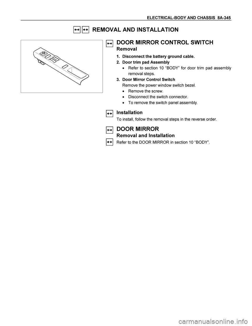
DOOR MIRROR CONTROL SWITCH
Removal
1. Disconnect the battery ground cable.
2. Door trim pad Assembly
� Refer to section 10 “BODY” for door trim pad assembly
removal steps.
3. Door Mirror Control Switch
Remove the power window switch bezel.
� Remove the screw.
� Disconnect the switch connector.
� To remove the switch panel assembly.
Installation
To install, follow the removal steps in the reverse order.
DOOR MIRROR
Removal and Installation
Refer to the DOOR MIRROR in section 10 “BODY”.
Page 1004 of 4264
8A-346 ELECTRICAL-BODY AND CHASSIS
INSPECTION AND REPAIR
Switch side
D-19
Door Mirror Control Switch
1. Switch side Connector Circuit
Check continuity between the switch connector terminals
while operating the door mirror control switch as shown in
the following table.
RTW48AMF000601
MV, MH, b, and e terminals have internal connections (circuitry).
4-point switch (Will not operate at intermediate positions.)
Harness side
D-19
2. Harness Side Connector Circuit
Remove the connector No.
D-19 of the mirror control
switch and check voltage and continuity of the harness side
connector.
� When there is no continuity at the terminal No. 2, 3, 9
and 10, it is considered that the circuit with terminal No.
7 (W/B) is defective.

RTW48AXF020401 & RTW48AXF020501")
 Control
Switch LH RH
1. Mirrors on th")

 direction
Checkpoint Trouble Cause Countermeasure
Replace the door mirror
cont")