ELECTRICAL-BODY AND CHASSIS 8A-347
� When there is no continuity at either one of the circuit
No, 5, 7, 8, or 10, the motor in the mirror of the circuit or
the circuit itself is defective.
Terminal
No. Wire
color Connection to Check item Connecting
terminal Check condition Standard
7 W/B LH mirror & RH
mirror Continuity 7-Ground - No continuity
4 R/Y Fuse C-11 (10A) Voltage 4-Ground Starter SW “ACC”
position Approx.
12V
10 W/R RH mirror-LH/RH 10-7 -
2 B/W RH mirror-Up/Down 2-7 -
3 B/R LH mirror-Up/Down Continuity 3-7 - Continuity
8 B Ground 8-Ground -
9 W/G LH mirror-LH/RH 9-7 -
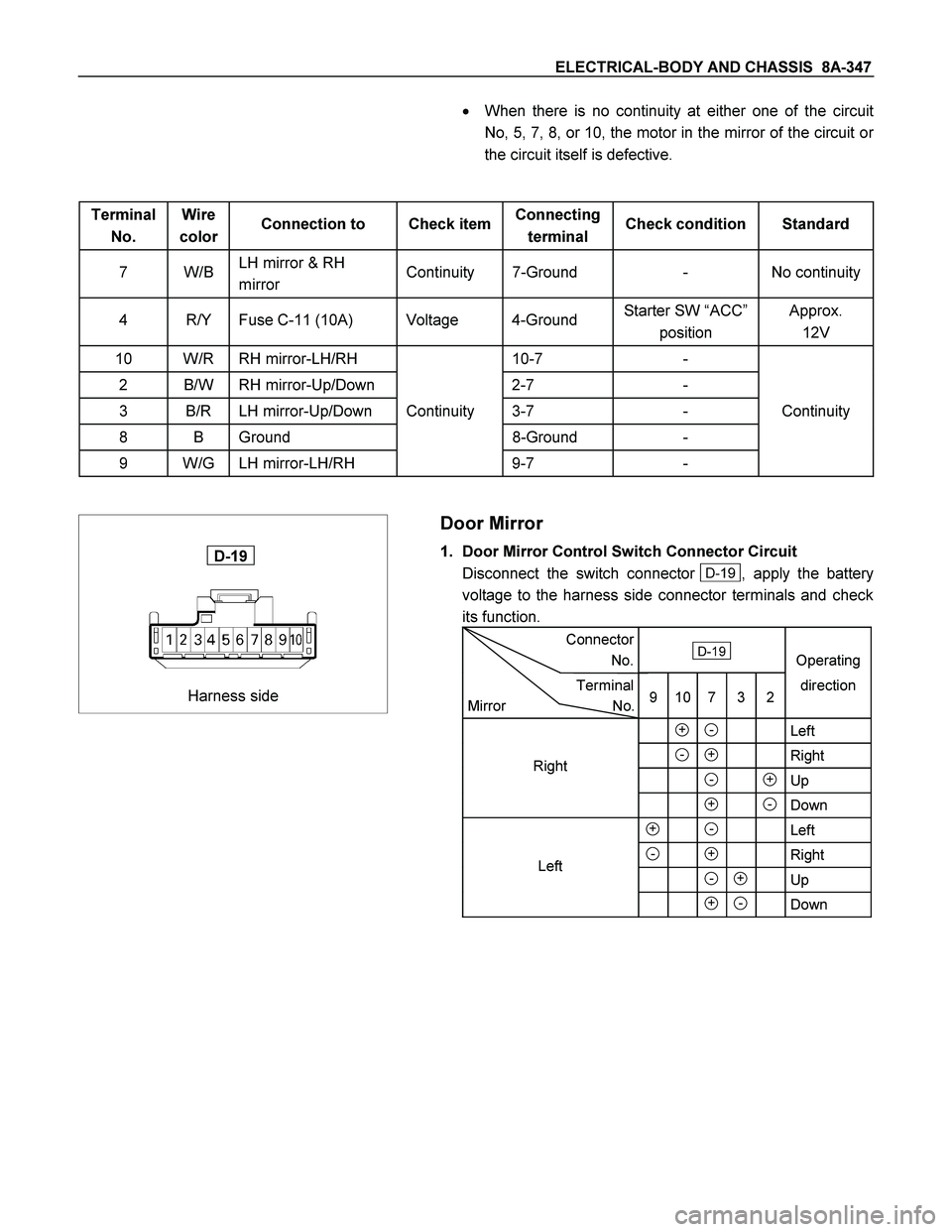
Harness side
D-19
Door Mirror
1. Door Mirror Control Switch Connector Circuit
Disconnect the switch connector
D-19 , apply the battery
voltage to the harness side connector terminals and check
its function.
Connector
No. D-19
Operating
Terminal
Mirror No.9 10 7 3 2direction
+ - Left
- + Right
- +Up
+ -Down
+ - Left
- + Right
- + Up
+ - Down
Left Right
8A-348 ELECTRICAL-BODY AND CHASSIS
Door mirror side
D-2 D-7
2. Door Mirror Connector Circuit
Disconnect the door mirror connector, apply the battery
voltage to the door mirror side connector (
D-2 and D-7)
terminals and check its function.
Connector No.
D-2 D-7
Terminal No.
Operation 1 2 4
Up - +
Down + -
Left + -
Right - +
8A-426 ELECTRICAL-BODY AND CHASSIS
No. Connector face No. Connector face
D-1
Brown
Power window motor-RH D-10
WhitePower window switch passenger side
D-2
White
Remote mirror-RH D-11
BrownPower window motor Rear-LH
D-3
Black
Front speaker-RH D-12
WhitePower window switch Rear-LH
D-4
Black
Door lock actuator driver side D-13
BlackRear speaker-LH
D-5
White
Power window driver side D-14
BlackDoor lock actuator Rear-LH
D-6
Brown
Power window motor-LH D-15
BrownPower window motor Rear-RH
D-7
White
Remote mirror-LH D-16
WhitePower window switch-RH
D-8
Black
Speaker-LH D-17
BlackRear speaker-RH
D-9
Black
Door lock actuator passenger side
(keyless & antitheft) D-18
BlackDoor lock actuator Rear-RH
D-9
Black
Door lock actuator passenger side D-19
WhiteRemote mirror switch driver side