Page 287 of 4264
FRONT WHEEL DRIVE 4C1-67
TROUBLESHOOTING
Refer to this Section to quickly diagnose and repair front axle problems. Each troubleshooting chart has three
headings arranged from left to right.
(1) Checkpoint (2) Trouble Cause (3) Countermeasure
This Section is divided into ten sub-sections:
4�
�� �2 Model
1. Wanders and pulls
2. Front wheel shimmy
4�
�� �4 Model
1. Oil leak at front axle
2. Oil leak at pinion shaft
3. Noises in front axle drive shaft joint
4. Noises in front axle
5. Wanders and pulls
6. Front wheel shimmy
Propeller shaft
1. Noise
2. Vibration
Page 290 of 4264
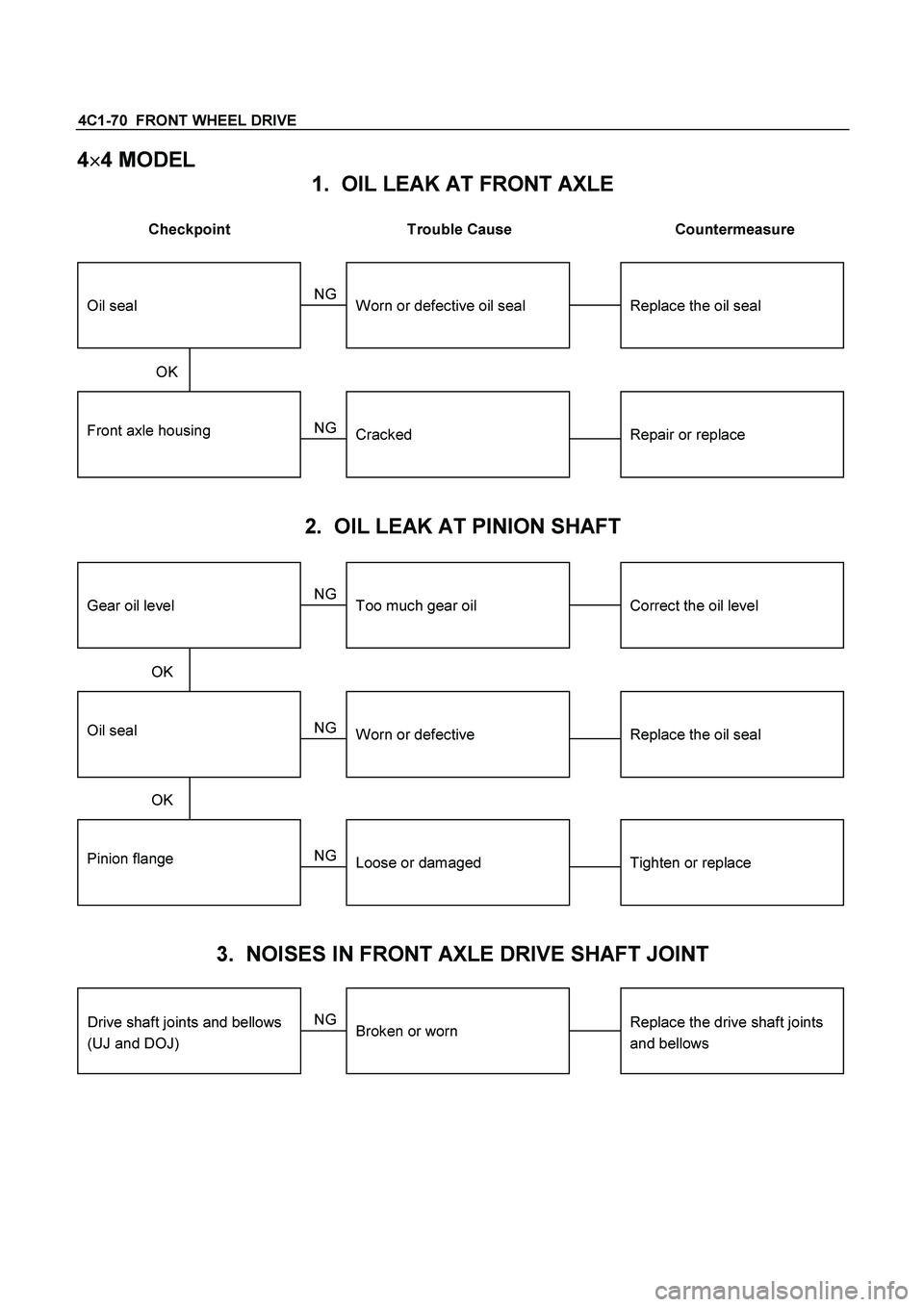
4C1-70 FRONT WHEEL DRIVE
4�
�� �
4 MODEL
1. OIL LEAK AT FRONT AXLE
Checkpoint Trouble Cause Countermeasure
Front axle housingRepair or replaceCracked
Replace the oil sealWorn or defective oil seal
NG NG
OKOil seal
2. OIL LEAK AT PINION SHAFT
Oil sealReplace the oil sealWorn or defective
Correct the oil levelToo much gear oil
NG NG
OKGear oil level
Pinion flangeTighten or replaceLoose or damaged NG OK
3. NOISES IN FRONT AXLE DRIVE SHAFT JOINT
Replace the drive shaft joints
and bellows
Broken or worn
NG
Drive shaft joints and bellows
(UJ and DOJ)
Page 291 of 4264
FRONT WHEEL DRIVE 4C1-71
4. NOISES IN FRONT AXLE
Checkpoint Trouble Cause Countermeasure
Replenish the gear oilInsufficient gear oil NG
Replace the wheel bearing
Replace the pinion shaft
bearing
Replace the ring gear pinion
gear or side gear
Replace the gear oil
Wheel bearingWorn
Pinion shaft bearingWorn
Worn or chipped
Wrong or poor grade gear oil
Ring gear, pinion gear or side
gear
Adjust the backlashDrive pinion to ring gear
backlashToo much or too little backlash
NG NG NG NG NG
OK OK
OK
OK
Oil level
Tighten or replaceDifferential bearingLoose or worn NG OK
Page 296 of 4264
4C1-76 FRONT WHEEL DRIVE
ITEM NO. ILLUSTRATION PART NO. PART NAME
FAL-41
5-8840-2089-0
(J-23597-9)
Nut & bolt
FAL-36
5-8840-2087-0
(J-23597-7)
Gauge plate
FAL-42
5-8840-0126-0
(J-8001)
Dial indicator
FAL-43
5-8840-0128-0
(J-23597-1)
Arbor
FAL-38
5-8840-2088-0
(J-23597-8)
Disc (2 pcs. required)
FAL-59
9-8522-1165-0
(J-6133-01)
Pinion bearing installer
(for 4WD)
FAL-52
9-8522-1275-0
(J-24250)
Pinion oil seal installer
FAL-56
9-8522-1164-0
(J-24244)
Side bearing installer
FAL-57
5-8522-0053-0
(J-29016)
Outer bearing installer
(for 2WD)
Page 297 of 4264
FRONT WHEEL DRIVE 4C1-77
ITEM NO. ILLUSTRATION PART NO. PART NAME
FAL-58
5-8522-0054-0
(J-29015)
Inner bearing installer
(for 2WD)
FAL-54
5-8522-0051-0
(J-33161)
Hub oil seal installer
(for 2WD)
FAL-62
5-8840-2117-0
(J-36827)
Hub nut wrench
FAL-17
5-8840-2119-0
(J-36829)
Outer bearing inner race
installer (for 4WD)
FAL-19
5-8840-2120-0
(J-36830)
Oil seal installer (for 4WD)
FAL-18
5-8522-0054-0
(J-29015)
Outer bearing outer race
installer (for 4WD)
FAL-61
5-8840-2137-0
(J-38194)
Inner cam installer
FAL-39
5-8840-2126-0
Auto locking shim gauge
(for 4WD)
FAL-60
5-8840-2125-0
Snap ring installer
(for 4WD)
Page 302 of 4264
4C2-4 SHIFT ON THE FLY SYSTEM
Shift On The Fly System and Association Parts
RTW440LF000701
Disassembly steps
1. Filler plug
2. Bolt
3. Front axle drive shaft (LH side)
4. Bolt
5. Actuator assembly
6. Bolt
7. Housing
8. Sleeve
9. Clutch gear
10. Snap ring
11. Inner shaft
12. Snap ring
13. Inner shaft bearing
14. Needing bearing
15. Oil seal
Reassembly steps
To reassemble, follow the disassembly steps in
the reverse order.
Page 303 of 4264
SHIFT ON THE FLY SYSTEM 4C2-5
DISASSEMBLY
1. Filler Plug
Remove filler plug and packing and drain oil.
2. Bolt
Loosen mounting bracket fitting bolts and remove front axle
drive shaft from front axle case.
3. Front Axle Drive Shaft (LH side)
4. Bolt
Loosen actuator ASM fitting bolts.
5. Actuator Assembly
Draw out actuator ASM.
6. Bolt
Remove hosing fitting bolts.
7. Housing
8. Sleeve
9. Clutch Gear
412RW017
10. Snap Ring
Remove snap ring from front axle case by using a snap ring
pliers.
11.Inner Shaft
Take out inner shaft from front axle case.
412RW016
12.Snap Ring
Remove snap ring from inner shaft by using a snap ring
pliers.
412RW015
13.Inner Shaft Bearing
Remove inner shaft bearing by using a special tool and
press.
Remove : 5-8840-2197-0 (J-37452)
NOTE:
Be careful not to damage the shaft.
Page 304 of 4264

Sliding hammer : 5-")
4C2-6 SHIFT ON THE FLY SYSTEM
412RS045
14.Needle Bearing
Remove needle bearing from inner shaft by using a special
tool.
Remover : 5-8840-0027-0 (J-26941)
Sliding hammer : 5-8840-0084-0 (J-2619-01)
NOTE:
Be careful not to damage the shaft.
15.Oil Seal
Remove oil seal from front axle case.
NOTE:
Be careful not to damage the front axle case.
Inspection and Repair
Inspect the removed parts. If there are abnormalities such as
wear and damage, take corrective action or replace.
Visual Check
�
Check and see if the inner shaft has such
abnormalities as wear and damage.
412RW014
412RS008
�
When inspecting the inner shaft, be sure to check and
see if its splined part is twisted, worn, or cracked. If so,
replace with a new shaft. In case such an abnormality
in its gear part (a slide with sleeve), replace the shaft.
412RS026
Inner Shaft Run-Out
With both end centers supported, rotate the shaft slowly
and measure deflection with a dial gauge.
Inner Shaft Run-Out (Limit) mm (in)
0.5 (0.02)
NOTE:
Do not heat the shaft to correct its bend.
")


Nut & bolt
FAL-36
5-8840-2087-0
(J-23597-7)
Gauge plate
FAL-4")

Inner bearing installer
(for 2WD)
FAL-54
5-8522-0051-0
(J-33161)
Hub oi")

4. Bolt")
