Page 273 of 4264
FRONT WHEEL DRIVE 4C1-53
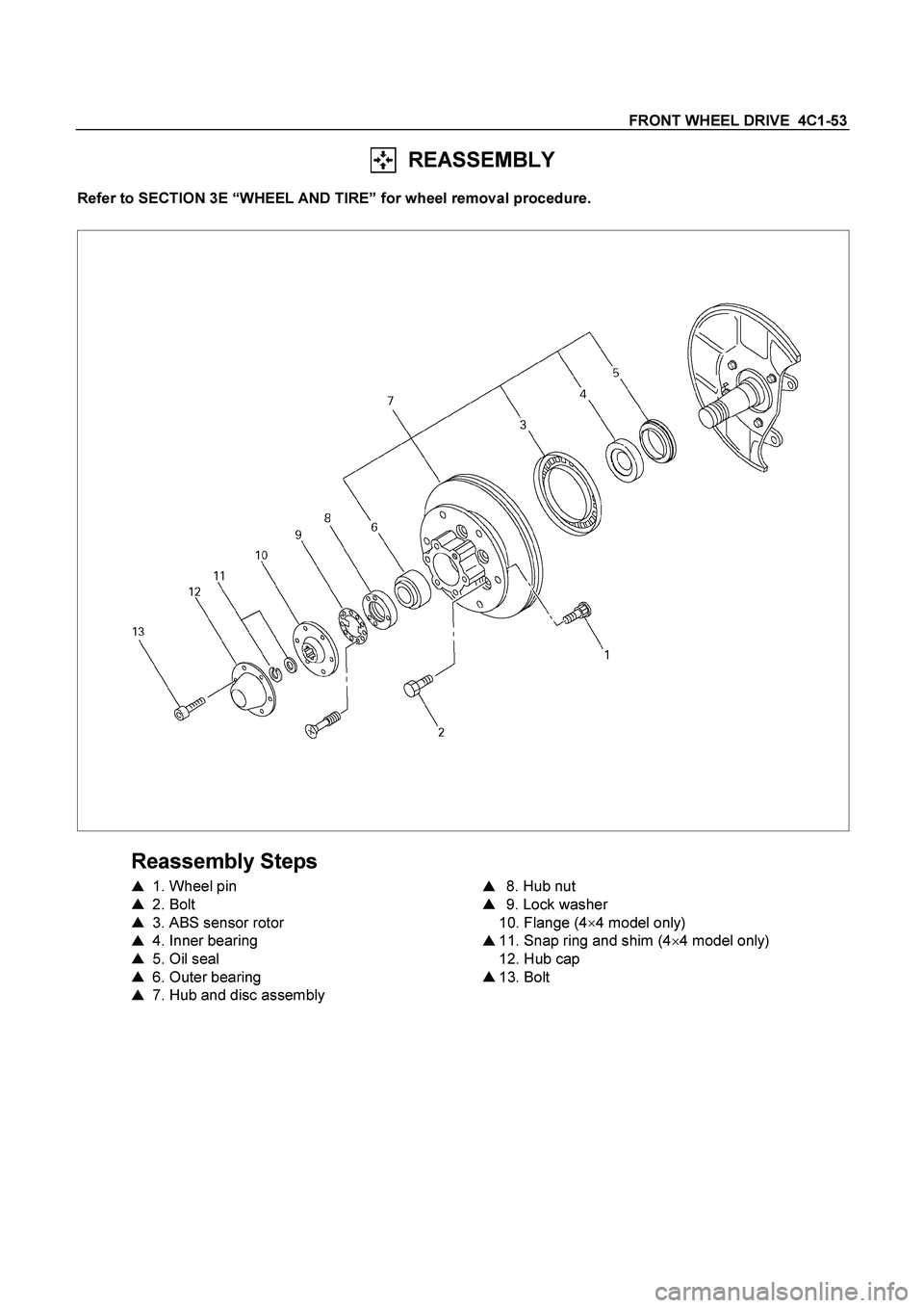
REASSEMBLY
Refer to SECTION 3E “WHEEL AND TIRE” for wheel removal procedure.
Reassembly Steps
�
1. Wheel pin
�
2. Bolt
�
3. ABS sensor rotor
�
4. Inner bearing
�
5. Oil seal
�
6. Outer bearing
�
7. Hub and disc assembly
�
8. Hub nut
�
9. Lock washer
10. Flange (4�
4 model only)
�
11. Snap ring and shim (4�
4 model only)
12. Hub cap
�
13. Bolt
Page 275 of 4264
FRONT WHEEL DRIVE 4C1-55
5. Oil Seal
Installer : 5-8840-2120-0
(J-36830)
Grip : 5-8840-0007-0
(J-8092)
Apply grease (Besco L-2 or equivalent) to the lip portion.
Discard the used oil seal and install a new one.
RTW44CSH000101
6. Outer bearing
Outer race ; outer bearing
Install the outer race by driving it into the hub.
Installer : 5-8522-0054-0
(J-29015)
Grip : 5-8840-0007-0
(J-8092)
7. Hub and Disc Assembly
(1) Apply grease in the hub.
(2) Apply grease (Besco L-2 or equivalent) to the outer and
inner bearing.
g(oz)
Hub 35 (1.23)
Outer bearing 10 (0.35)
Inner bearing 15 (0.53)
8. Hub Nut
(1) Turn the place where there is a chamfer in the tapped hole
to the outer side, and attach the nut.
Wrench : 5-8840-2117-0
(J-36827)
Page 276 of 4264
, then
loosen the nut to the full.
Tighten the hub nut at the value given below, using a s")
4C1-56 FRONT WHEEL DRIVE
Preload Adjustment
Tighten the hub nut at 29.4 N�m (3 kgf�m / 21.716 lb.ft), then
loosen the nut to the full.
Tighten the hub nut at the value given below, using a spring
scale on the wheel pin.
Bearing Preload N(lb)
New bearing and New oil seal 20 - 25 (4.4 - 5.5)
Used bearing and New oil seal 12 - 18 (2.68 - 4.0)
If the measured bearing preload is outside the specifications,
adjust it by loosening or tightening the bearing nut.
9. Lock Washer
Turn the side with larger diameter of the tapered bore to the
vehicle outer side, and attach the washer.
If the bolt holes in the lock plate are not aligned with the
corresponding holes in the nut, reverse the lock plate.
If the bolt holes are still out of alignment, turn in the nut just
enough to obtain alignment,. Screw is to be fastened tightly so
its head may come lower than the surface of the washer.
11. Snap ring, shims (4
�
�� �4 model only)
Adjust the clearance between the flange and the snap ring.
Clearance mm(in)
0 - 0.2 (0 - 0.08)
Adjust shims available
mm(in)
0.2, 0.3, 0.5, 1.0
(0.008, 0.011, 0.020, 0.039)
RTW440SH000901
13.
Bolt
Torque N�m (kgf�m/lb�ft
)
59 (6.0 / 43)
Page 277 of 4264
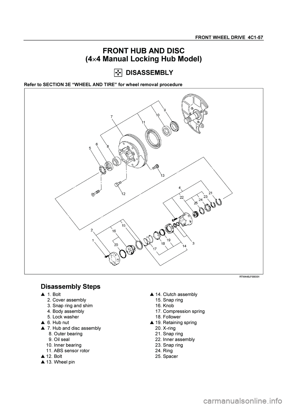
FRONT WHEEL DRIVE 4C1-57
FRONT HUB AND DISC
(4�
�� �4 Manual Locking Hub Model)
DISASSEMBLY
Refer to SECTION 3E “WHEEL AND TIRE” for wheel removal procedure
RTW440LF000301
Disassembly Steps
�
1. Bolt
2. Cover assembly
3. Snap ring and shim
4. Body assembly
5. Lock washer
�
6. Hub nut
�
7. Hub and disc assembly
8. Outer bearing
9. Oil seal
10. Inner bearing
11. ABS sensor rotor
�
12. Bolt
�
13. Wheel pin
�
14. Clutch assembly
15. Snap ring
16. Knob
17. Compression spring
18. Follower
�
19. Retaining spring
20. X-ring
21. Snap ring
22. Inner assembly
23. Snap ring
24. Ring
25. Spacer
Page 280 of 4264
4C1-60 FRONT WHEEL DRIVE
INSPECTION AND REPAIR
Make necessary correction or parts replacement if wear, damage or any other abnormal conditions are found
through inspection.
For inspection and servicing of disc caliper, and relative parts, and ABS parts, refer to Section Brakes.
�
Hub
� Hub bearing, oil seal
�
Knuckle spindle
�
Disc
�
Caliper
�
ABS sensor rotor
�
Cap, Hub flange, Shim, Snap ring
�
Free wheeling hub parts (Option)
� Clutch, Knob, follower, inner, ring and
spring
Visual Check
Check the following parts for wear, damage or other abnormal
conditions.
Page 281 of 4264
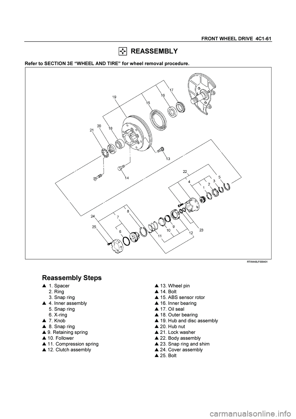
FRONT WHEEL DRIVE 4C1-61
REASSEMBLY
Refer to SECTION 3E “WHEEL AND TIRE” for wheel removal procedure.
RTW440LF000401
Reassembly Steps
�
1. Spacer
2. Ring
3. Snap ring
�
4. Inner assembly
5. Snap ring
6. X-ring
�
7. Knob
�
8. Snap ring
�
9. Retaining spring
�
10. Follower
�
11. Compression spring
�
12. Clutch assembly
�
13. Wheel pin
�
14. Bolt
�
15. ABS sensor rotor
�
16. Inner bearing
�
17. Oil seal
�
18. Outer bearing
�
19. Hub and disc assembly
�
20. Hub nut
�
21. Lock washer
�
22. Body assembly
�
23. Snap ring and shim
�
24. Cover assembly
�
25. Bolt
Page 284 of 4264
4C1-64 FRONT WHEEL DRIVE
17. Oil Seal
Installer : 5-8840-2120-0
(J-36830)
Grip : 5-8840-0007-0
(J-8092)
Apply grease (Besco L-2 or equivalent) to the lip portion.
Discard the used oil seal and install a new one.
RTW44CSH000201
18. Outer bearing
Outer race ; outer bearing
Install the outer race by driving it into the hub.
Installer : 5-8522-0054-0
(J-29015)
Grip : 5-8840-0007-0
(J-8092)
19. Hub and Disc Assembly
(1) Apply grease in the hub.
(2) Apply grease (Besco L-2 or equivalent) to the outer and
inner bearing.
g(oz)
Hub 35 (1.23)
Outer bearing 10 (0.35)
Inner bearing 15 (0.53)
20. Hub Nut
(1) Turn the place where there is a chamfer in the tapped hole
to the outer side, and attach the nut.
Wrench : 5-8840-2117-0
(J-36827)
Page 285 of 4264
, then
loosen the nut to the full.
Tighten the hub nut at the value given below, using a s")
FRONT WHEEL DRIVE 4C1-65
Preload Adjustment
Tighten the hub nut at 29.4 N�m (3 kgf�m / 21.716 lb.ft), then
loosen the nut to the full.
Tighten the hub nut at the value given below, using a spring
scale on the wheel pin.
Bearing Preload N(lb)
New bearing and New oil seal 20 - 25 (4.4 - 5.5)
Used bearing and New oil seal 12 - 18 (2.68 - 4.0)
If the measured bearing preload is outside the specifications,
adjust it by loosening or tightening the bearing nut.
21. Lock Washer
Turn the side with larger diameter of the tapered bore to the
vehicle outer side, and attach the washer.
If the bolt holes in the lock plate are not aligned with the
corresponding holes in the nut, reverse the lock plate.
If the bolt holes are still out of alignment, turn in the nut just
enough to obtain alignment,. Screw is to be fastened tightly so
its head may come lower than the surface of the washer.
22. Body Assembly
Apply adhesive (Loctite 15 or equivalent) to the both joining
faces.
23. Snap Ring and Shims
Adjust the clearance between the free wheeling hub body and
the snap ring.
Clearance mm(in)
0 - 0.2 (0 - 0.08)
Adjust Shims Available mm(in)
0.2, 0.3, 0.5, 1.0
(0.008, 0.011, 0.020, 0.039)
24. Cover Assembly
Align stopper nails to grooves of body.

Grip : 5-8840-0007-0
(J-8092)
Apply grease (Besco L-2 or equivalent) to the lip portion.
Discard the used oil seal")


Grip : 5-8840-0007-0
(J-8092)
Apply grease (Besco L-2 or equivalent) to the lip portion.
Discard the used oil sea")