Page 190 of 4264

4B-26 REAR AXLE
4. Place the shim on the drive pinion, then install the
inner bearing onto the pinion by using installer 9-
8522-1165-0 and a press.
Note:
Do not apply pressure to the roller cage. Apply
NOTE: pressure only to the inner race.
425L100008
5. Install collapsible spacer. Discard the used
collapsible spacer and install a new one.
6. Install drive pinion shaft assembly.
7. Install outer bearing and oil seal.
8. Use oil seal installer 5-8840-2165-0 to install a
new oil seal that has grease on seal lip.
415RW029
9. Install flange assembly.
10. Install flange nut.
a. Apply lubricant to the pinion threads.
b. Using the pinion flange holder 5-8840-0133-0,
tighten the nut only enough to remove the shaft
end play.
Note :
Discard used flange nut and install new one.
415RW040
c. Adjust pinion bearing preload.
�
Measure the bearing preload by using a torque
meter and note the scale reading required to
rotate the flange.
�
Continue tightening flange nut until the specified
starting torque is obtained.
Starting torque :
0.7-1.3 N�
m (0.07-0.13 kg�
m/6-11 lb�
ft)
Page 197 of 4264
REAR AXLE 4B-33
Disassembly
1. Remove bolt.
2. Remove ring gear.
3. Drive out lock pin using a long drift Punch.
425RS042
4. Check the amount of backlash between pinion
gear on side gear before removal of cross pin.
Backlash :
0.13-0.18 mm (0.005–0.007 in)
5. Remove the cross pin by using a brass drift
punch and hammer.
425RS043
6. Take out pinion gear, side gear and thrust
washer.
Inspection and Repair
Make necessary correction or parts replacement if
wear, damage, corrosion or any other abnormal
conditions are found through inspection.
Check the following parts:
�
Ring gear, pinion gear
�
Bearing
�
Side gear, pinion gear, cross pin
�
Differential cage, carrier
�
Thrust washer
�
Oil seal
Clearance between pinion gear and cross pin:
mm(in)
Standard Limit
0.06 - 0.12
(0.002 - 0.005) 0.2 (0.008)
425L100012
Clearance between side gear and differential cage.
mm(in)
Standard Limit
0.05 - 0.11
(0.002 - 0.004) 0.15 (0.006)
Page 198 of 4264
4B-34 REAR AXLE
425R300010
Play in splines between the side gear and axle shafts.
mm(in)
Standard Limit
0.08 - 0.38
(0.003 - 0.015) 0.5 (0.02)
425L100014
Differential cage
Check the ring gear the side gear fitting faces and the
cross pin hole for scores or roughness. Correct as
necessary. Slight scores or roughness may be
corrected with an oil stone or fine sand paper.
425R300006
Ring gear replacement:
1. The ring gear should always be replaced with the
drive pinion as a set.
2. Discard use bolts and install new ones.
3.
Apply LOCTITE 271 on bolt from the end of thread
to the middle of straight portion.
4. Tighten the fixing bolts in a diagonal sequence as
illustrated.
Torque : 108 N�m (11 kg�m/80 lb�ft)
425RW033
Page 202 of 4264

4B-38 REAR AXLE
Inspection and Repair
Make all necessary adjustments, repairs, and part
replacements if wear, damage, rust or other problems
are discovered during inspection.
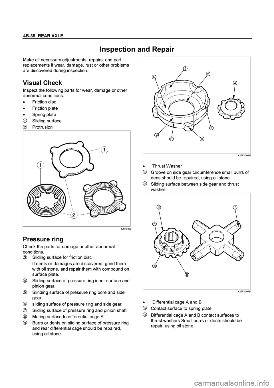
Visual Check
Inspect the following parts for wear, damage or other
abnormal conditions.
�
Friction disc
�
Friction plate
�
Spring plate
1 Sliding surface
2 Protrusion
425RS056
Pressure ring
Check the parts for damage or other abnormal
conditions.
3 Sliding surface for friction disc
If dents or damages are discovered, grind them
with oil stone, and repair them with compound on
surface plate.
4 Sliding surface of pressure ring inner surface and
pinion gear.
5 Slinding surface of pressure ring bore and side
gear.
6 sliding surface of pressure ring and side gear.
7 Sliding surface of pressure ring and pinion shaft.
8 Mating surface to differential cage A.
9 Burrs or dents on sliding surface of pressure ring
and rear differential cage should be repaired,
using oil stone.
425RY00022
�
Thrust Washer
10 Groove on side gear circumference small burrs of
dens should be repaired, using oil stone.
11 Sliding surface between side gear and thrust
washer.
425RY00024
�
Differential cage A and B
12 Contact surface to spring plate
13 Differential cage A and B contact surfaces to
thrust washers Small burrs or dents should be
repair, using oil stone.
Page 205 of 4264

REAR AXLE 4B-41
425RS066
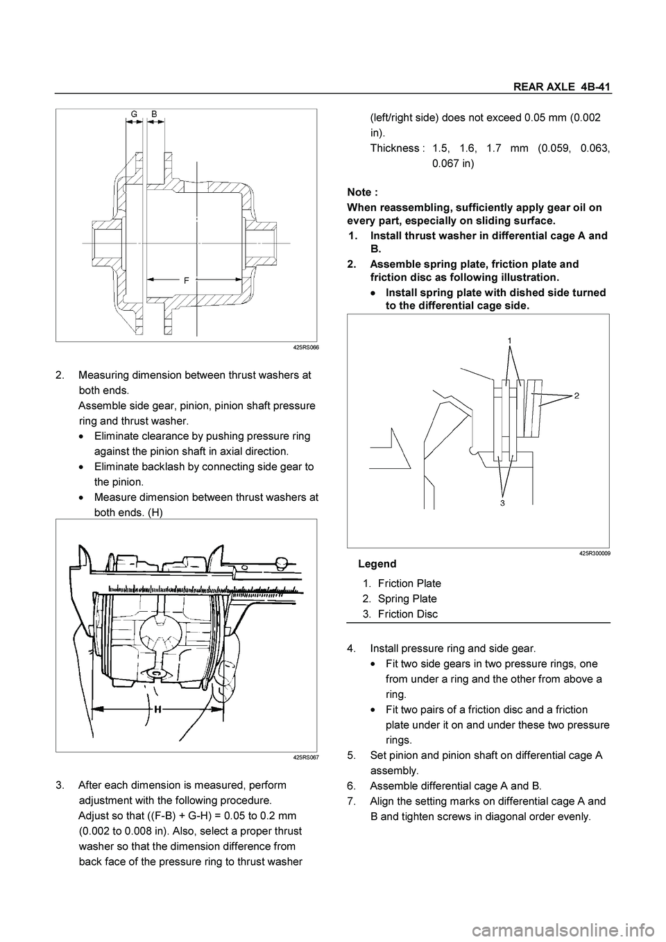
2. Measuring dimension between thrust washers at
both ends.
Assemble side gear, pinion, pinion shaft pressure
ring and thrust washer.
� Eliminate clearance by pushing pressure ring
against the pinion shaft in axial direction.
�
Eliminate backlash by connecting side gear to
the pinion.
�
Measure dimension between thrust washers at
both ends. (H)
425RS067
3. After each dimension is measured, perform
adjustment with the following procedure.
Adjust so that ((F-B) + G-H) = 0.05 to 0.2 mm
(0.002 to 0.008 in). Also, select a proper thrust
washer so that the dimension difference from
back face of the pressure ring to thrust washer
(left/right side) does not exceed 0.05 mm (0.002
in).
Thickness : 1.5, 1.6, 1.7 mm (0.059, 0.063,
0.067 in)
Note :
When reassembling, sufficiently apply gear oil on
every part, especially on sliding surface.
1. Install thrust washer in differential cage A and
B.
2. Assemble spring plate, friction plate and
friction disc as following illustration.
�
�� � Install spring plate with dished side turned
to the differential cage side.
425R300009
Legend
1. Friction Plate
2. Spring Plate
3. Friction Disc
4. Install pressure ring and side gear.
�
Fit two side gears in two pressure rings, one
from under a ring and the other from above a
ring.
�
Fit two pairs of a friction disc and a friction
plate under it on and under these two pressure
rings.
5. Set pinion and pinion shaft on differential cage A
assembly.
6. Assemble differential cage A and B.
7. Align the setting marks on differential cage A and
B and tighten screws in diagonal order evenly.
Page 207 of 4264
REAR AXLE 4B-43
TROUBLESHOOTING
Refer to this Section to quickly diagnose and repair
rear axle problems.
Each troubleshooting chart has three headings
arranged from left to right.
(1) Checkpoint
(2) Trouble Cause
(3) Countermeasure
This Section is divided into five sub-sections:
1. Abnormal Rear Axle Noise
1) Noise when the engine is driving the vehicle
2) Noise when the vehicle is coasting
3) Intermittent noise
4) Noise when the vehicle is turning
5) Constant noise
2. Vibration
3. Oil Leakage
1) Differential carrier leakage
2) Axle case leakage
3) Axle case to inside hub leakage
4) Axle case to inside brake drum leakage
4. Power Not Being Transmitted to the Wheels
(Propeller Shaft Operation is Normal)
Page 208 of 4264
4B-44 REAR AXLE
1. ABNORMAL REAR AXLE NOISE
1) Noise when the Engine is Driving the Vehicle
Checkpoint Trouble Cause Countermeasure
Replenish the gear oilInsufficient gear oil NG
Differential side bearingAdjust the differential side
bearing preload
Replace the drive pinion
bearings
Adjust the drive pinion bearing
preload
Replace the gear oil
Loose differential side
bearings
Worn drive pinion bearings
Loose drive pinion bearings
Wrong or poor grade gear oil
Drive pinion to ring gear
backlash
Drive pinion end play
Adjust the backlashToo much or too little backlash
Continued on the next pageOK OK
NG NG NG NG NG
OK
OK
Rear axle gear oil
Replace the differential side
bearingsWorn differential side bearings NG
Page 212 of 4264
4B-48 REAR AXLE
5) Constant Noise
Checkpoint Trouble Cause Countermeasure
Replace the rear axle shaftBent rear axle shaft NG
Replace the side bearing
Replace the drive pinion
bearing
Replace the drive pinion and
the ring gear as a set
Replace the drive pinion and
the ring gear as a set
Flat spot on the side bearing
oil seal
BearingFlat spot on the drive pinion
Flat spot on the gear teeth
pilot bearing wear
Drive pinionFlat spot on the drive pinion
gear teeth
Ring gear
Replace the drive pinion and
the ring gear as a setWorn pinion splines oil seal
NG NG NG NG NG
OK OK
OK
Rear axle shaft