Page 214 of 4264
4B-50 REAR AXLE
3. OIL LEAKAGE
1) Differential Carrier Leakage
Checkpoint Trouble Cause Countermeasure
Correct the oil levelToo much gear oil NG
Reapply the liquid gasket
and/or tighten the lock nut to
the specified torque
Reapply the liquid gasket
Tighten the bolts to the
specified torque
Replace the oil seal
Ring gear thrust boltLoose lock nut and/or liquid
Liquid gasket seal bed
Loose bolts
Oil sealWorn or defective oil seal
Differential carrier
Clean the air breatherAir breatherClogged air breather
NG NG NG NG NG
OK OK OK
OK
Gear oil level
Page 215 of 4264
REAR AXLE 4B-51
2) Axle Case Leakage
Checkpoint Trouble Cause Countermeasure
Tighten the drain plug and/or
replace the gasket(s)Loose drain plug and/or
defective gasket(s) NG
Reapply the liquid gasket
Tighten the bolts to the
specified torque
Clean the air breather
Liquid gasket seal bad
Loose bolts
Air breatherClogged air breather
Differential carrier
Replace the axle caseAxle caseCracked axle case
NG NG NG NG
OK OK
OK
Oil filler and drain plug
Page 216 of 4264
4B-52 REAR AXLE
3) Axle Case to Inside Brake Drum Leakage
Checkpoint Trouble Cause Countermeasure
Replace the oil sealWorn or defective oil seal NGOil seal
Page 218 of 4264
4B-54 REAR AXLE
SPECIAL SERVICE TOOL
ITEM NO. ILLUSTRATION PART NO. PART NAME
5-8840-0079-0
Wheel Pin Remover
9-8522-1269-0
Oil Seal Installer
5-8840-2202-0
Oil Seal Installer
9-8522-1271-0
Support Stand
5-8840-0275-0
Holding Fixture
5-8840-0003-0
Holding Fixture Base
5-8840-0013-0
Remover
5-8840-0014-0
Remover
5-8840-2196-0
Adapter
Page 223 of 4264
FRONT WHEEL DRIVE 4C1-3
MAIN DATA AND SPECIFICATIONS
FRONT AXLE AND DIFFERENTIAL
Ring gear size mm (in) 194 (7.6)
Axle tube
Type It consists of the duce, a cast iron housing and the Axle tube.
Gear type Hypoid
Gear ratio (to 1) 4.100, 4.300, 4.555, 4.777, 5125
Differential type Two pinion
Specified gear oil (APL grade) GL-5
Oil capacity liter 1.4
(US/UK gal.) (0.4/0.33)
Axle shaft type Constant velocity joint (Birfield joint type and double offset joint).
FRONT PROPELLER SHAFT mm(in)
4�
4 Model
Engine Model 4JA1-T(L) 4JA1-TC 4JH1-TC C24SE 6VE1
Transmission Type 5M/T (MUA) 5M/T
(MUA) 4A/T 5M/T
(MUA) 5M/T
(MUA) 4A/T
Front Axle 194 mm �
�
�
�
�
Outside Diameter mm 40 40 40 40 40 40
(in) (1.57) (1.57) (1.57) (1.57) (1.57) (1.57)
Inside Diameter mm 32 32 32 32 32 32
(in) (1.26) (1.26) (1.26) (1.26) (1.26) (1.26)
Length (L) mm 607 607 676 586 586 607
(in) (23.90) (23.90) (26.61) (23.07) (23.07) (23.90)
Fix Bolt Size T/F M10 M10 M10 M10 M10 M10
Axle M10 M10 M10 M10 M10 M10
Page 227 of 4264
FRONT WHEEL DRIVE 4C1-7
SERVICING
Hub Bearing Preload at the Wheel Pin
4�
4, 4�
2 (High Ride Suspension) Model N (lb)
New bearing and New oil seal 20 - 25 (4.4 - 5.5)
Reuse bearing and New oil seal 12 - 18 (2.6 - 4.0)
4�2 (Except High Ride Suspension) Model N (lb)
New bearing and New oil seal 8 - 12 (1.8 - 2.2)
Reuse bearing and New oil seal 8 - 12 (1.8 - 2.2)
Page 235 of 4264

FRONT WHEEL DRIVE 4C1-15
Removal
1. Jack up the vehicle and support it using jack stand.
2. Remove the tire and wheel.
3. Remove the stone guard.
4. Remove the brake caliper fixing bolt and hang the caliper.
Refer to Disc Brakes in Brake section.
5. Remove the antilock brake system speed sensor.
Refer to Front Wheel Speed Sensor in Brake section.
6. Remove the hub and disc assembly.
Refer to Front Hub and Disc in this section.
7. Remove the propeller shaft, refer to Front Propeller Shaft in
this section.
8. Loosen the height control arm of the torsion bar, then
remove the torsion bar from lower control arm.
Refer to Torsion Bar in Suspension section.
9. Remove the suspension crossmember.
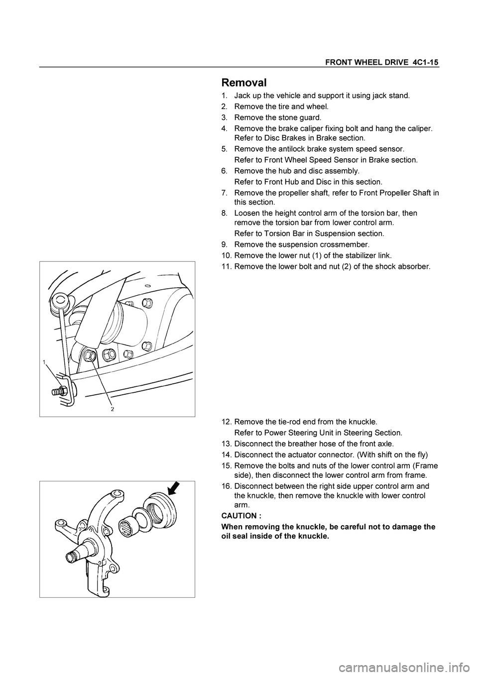
10. Remove the lower nut (1) of the stabilizer link.
11. Remove the lower bolt and nut (2) of the shock absorber.
12. Remove the tie-rod end from the knuckle.
Refer to Power Steering Unit in Steering Section.
13. Disconnect the breather hose of the front axle.
14. Disconnect the actuator connector. (With shift on the fly)
15. Remove the bolts and nuts of the lower control arm (Frame
side), then disconnect the lower control arm from frame.
16. Disconnect between the right side upper control arm and
the knuckle, then remove the knuckle with lower control
arm.
CAUTION :
When removing the knuckle, be careful not to damage the
oil seal inside of the knuckle.
Page 236 of 4264

4C1-16 FRONT WHEEL DRIVE
17. Support the differential case by the jack.
18. Remove the front axle mounting bolts and nuts, lower the
jack slowly. Remove the left side drive shaft end from the
knuckle, then lower the axle assembly from the vehicle.
CAUTION :
1. During the work, be sure that the axle assembly is
supported securly.
2. Be careful not to damage the bellows of the power
steering unit by interference.
3. Be careful not to damage the breater pipe and breater
pip bracket of the shift on the fly by interference.
Installation
1. Support the differential case by the jack.
2. Jack up the front drive axle assembly, install the left side
drive shaft to the knuckle, then install the mount bolts and
nuts.
CAUTION :
1. Be careful not to damage the bellows of the power
steering unit by interference.
2. Be careful not to damage the breater pipe and breater
pip bracket of the shift on the fly by interference.
3. When installing the drive shaft to the knuckle, be
careful not to damage the oil seal inside of the knuckle.
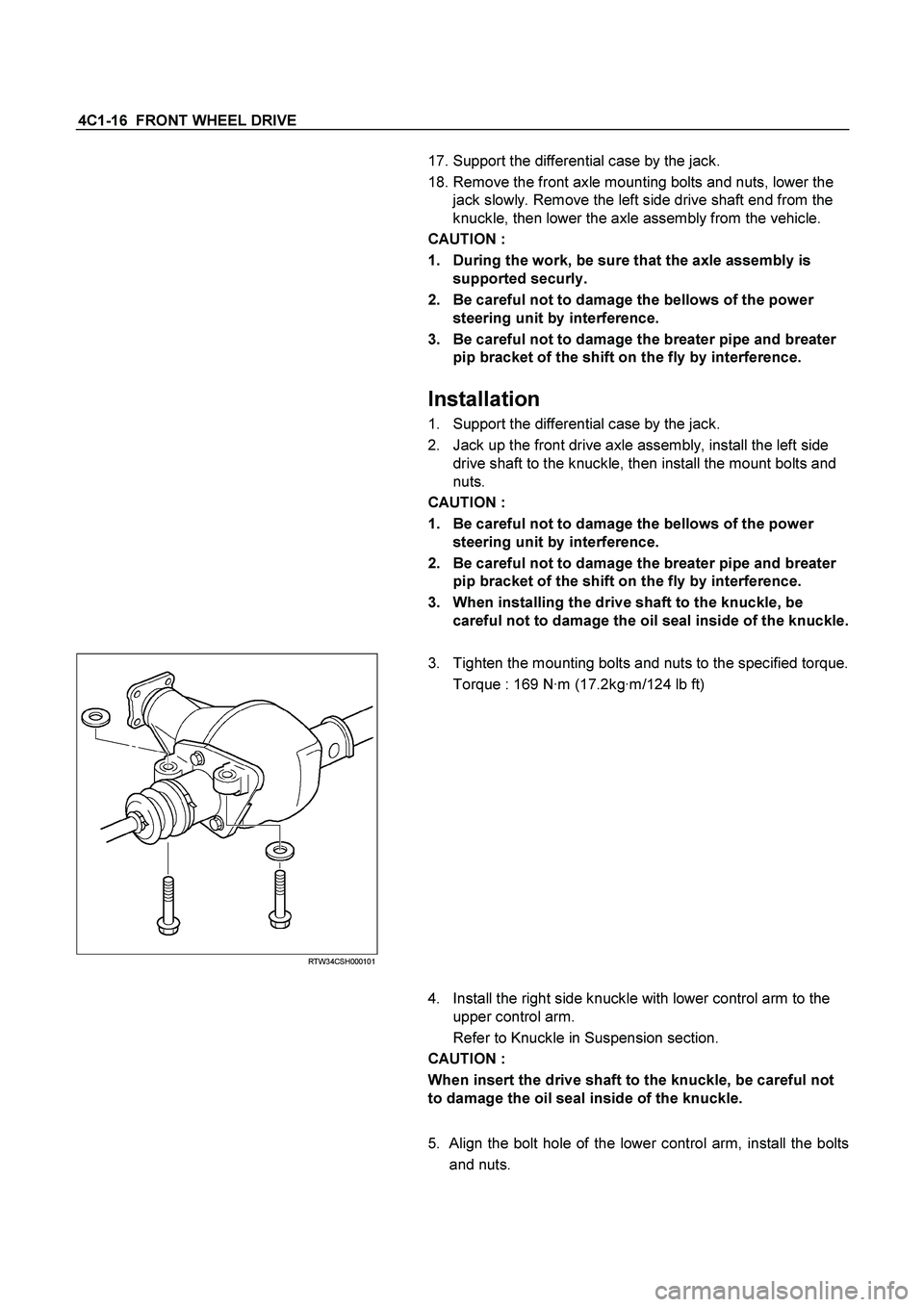
RTW34CSH000101
3. Tighten the mounting bolts and nuts to the specified torque.
Torque : 169 N·m (17.2kg·m/124 lb ft)
4. Install the right side knuckle with lower control arm to the
upper control arm.
Refer to Knuckle in Suspension section.
CAUTION :
When insert the drive shaft to the knuckle, be careful not
to damage the oil seal inside of the knuckle.
5. Align the bolt hole of the lower control arm, install the bolts
and nuts.