Page 1184 of 4264
6A – 44 ENGINE MECHANICAL
Removal
1. Clutch Assembly or Flex Plate
Remove the clutch assembly or the flex plate.
4JA1L RTW46ASH000801
2. Intake Pipe and Throttle Body (4JA1TC/4JH1TC only)
1) Loosen hose clamp between turbocharger and intake
duct.
2) Remove the rubber hose.
3) Remove the intake pipe and the throttle body.
(4JA1TC/4JH1TC only)
RTW36ASH000201
4JA1L
025R100008
3-1. EGR Pipe
1) Remove two bolts from the exhaust manifold.
2) Remove two nuts from the EGR valve adapter.
3) Remove the EGR pipe with gaskets.
RTW36ASH000301
3-2. EGR Cooler (EURO III model only) 4JA1TC/4JH1TC
4JH1TC
Page 1185 of 4264
ENGINE MECHANICAL 6A – 45
4JA1�L
RTW46ASH001001
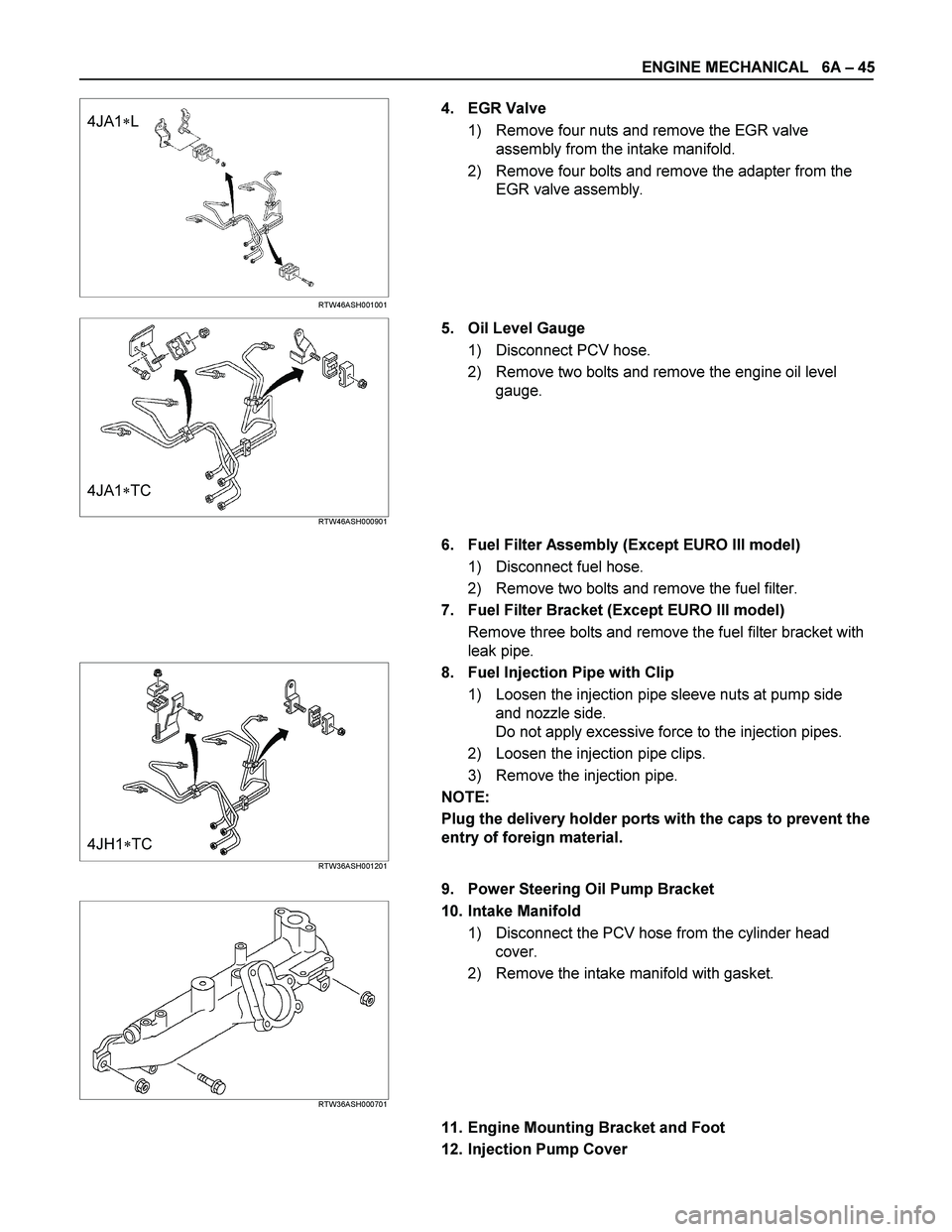
4. EGR Valve
1) Remove four nuts and remove the EGR valve
assembly from the intake manifold.
2) Remove four bolts and remove the adapter from the
EGR valve assembly.
4JA1�TC RTW46ASH000901
5. Oil Level Gauge
1) Disconnect PCV hose.
2) Remove two bolts and remove the engine oil level
gauge.
6. Fuel Filter Assembly (Except EURO III model)
1) Disconnect fuel hose.
2) Remove two bolts and remove the fuel filter.
7. Fuel Filter Bracket (Except EURO III model)
Remove three bolts and remove the fuel filter bracket with
leak pipe.
4JH1�TC RTW36ASH001201
8. Fuel Injection Pipe with Clip
1) Loosen the injection pipe sleeve nuts at pump side
and nozzle side.
Do not apply excessive force to the injection pipes.
2) Loosen the injection pipe clips.
3) Remove the injection pipe.
NOTE:
Plug the delivery holder ports with the caps to prevent the
entry of foreign material.
9. Power Steering Oil Pump Bracket
RTW36ASH000701
10. Intake Manifold
1) Disconnect the PCV hose from the cylinder head
cover.
2) Remove the intake manifold with gasket.
11. Engine Mounting Bracket and Foot
12. Injection Pump Cover
Page 1192 of 4264
6A – 52 ENGINE MECHANICAL
RTW36ASH000801
Idler Gear "A" End Play Measurement
Insert a feeler gauge between the idler gear and the thrust
collar to measure the gap and determine the idler gear
end play.
If the measured value exceeds the specified limit, the
thrust collar must be replaced.
Idler Gear End Play mm (in)
Standard Limit
0.07 (0.0028) 0.2 (0.0079)
4JA1T(L)
040R300009
14. Idle Gear Shaft
15. Crankshaft Timing Gear
4JA1TC/4JH1TC RTW36ASH001301
16. Injection Pump
1. Remove the injection pump cover (4JA1TC/4JH1TC
only).
2. Remove the injection pump bracket.
3. Pull the injection pump along with the injection pump
timing gear free toward the rear of the engine.
NOTE:
Plug the injection pump delivery ports with the caps to
prevent the entry of foreign material.
17. Flywheel
Loosen the flywheel bolts in numerical order a little at a
time.
Use the gear stoper to stop the flywheel gear.
Gear stoper: 5-8840-0214-0
18. Crank Case
19. Oil Pump With Oil Pipe
015RY00001
Page 1204 of 4264
6A – 64 ENGINE MECHANICAL
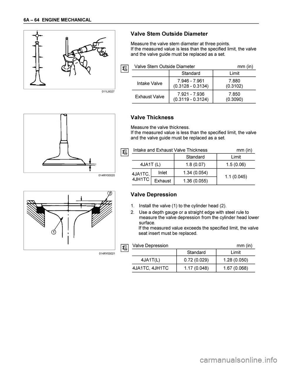
Valve Stem Outside Diameter
Measure the valve stem diameter at three points.
If the measured value is less than the specified limit, the valve
and the valve guide must be replaced as a set.
Valve Stem Outside Diameter mm (in)
Standard Limit
Intake Valve 7.946 - 7.961
(0.3128 - 0.3134) 7.880
(0.3102)
Exhaust Valve 7.921 - 7.936
(0.3119 - 0.3124) 7.850
(0.3090)
Valve Thickness
Measure the valve thickness.
If the measured value is less than the specified limit, the valve
and the valve guide must be replaced as a set.
Intake and Exhaust Valve Thickness mm (in)
Standard Limit
4JA1T (L) 1.8 (0.07) 1.5 (0.06)
Inlet 1.34 (0.054) 4JA1TC,
4JH1TC
Exhaust 1.36 (0.055) 1.1 (0.045)
Valve Depression
1. Install the valve (1) to the cylinder head (2).
2. Use a depth gauge or a straight edge with steel rule to
measure the valve depression from the cylinder head lowe
r
surface.
If the measured value exceeds the specified limit, the valve
seat insert must be replaced.
Valve Depression mm (in)
Standard Limit
4JA1T(L) 0.72 (0.029) 1.28 (0.050)
4JA1TC, 4JH1TC 1.17 (0.048) 1.67 (0.068)
011LX027
014RY00020
014RY00021
Page 1207 of 4264
ENGINE MECHANICAL 6A – 67
Valve Spring Free Height
Use a vernier caliper to measure the valve spring free height.
If the measured value is less than the specified limit, the valve
spring must be replaced.
Spring Free Height mm (in)
Standard Limit
4JA1T (L)
4JA1TC,
4JH1TC Single spring 48.0 (1.89) 47.1 (1.85)
Valve Spring Squareness
Use a surface plate and a square to measure the valve spring
squareness.
If the measured value exceeds the specified limit, the valve
spring must be replaced.
Spring Squareness mm (in)
Limit
4JA1T (L)
4JA1TC,
4JH1TC Single spring 1.7 (0.070)
Valve Spring Tension
Use a spring tester to measure the valve spring tension.
If the measured value is less than the specified limit, the valve
spring must be replaced.
Valve Spring Tension N (kg/lb)
Compressed
Height Standard Limit
4JA1T (L)
4JA1TC,
4JH1TCSingle
spring38.9mm
(1.53in) 296.0
(30.2/66.4) 257.7
(26.3/57.9)
011LX024
014RY00025
011LX026
Page 1209 of 4264
ENGINE MECHANICAL 6A – 69
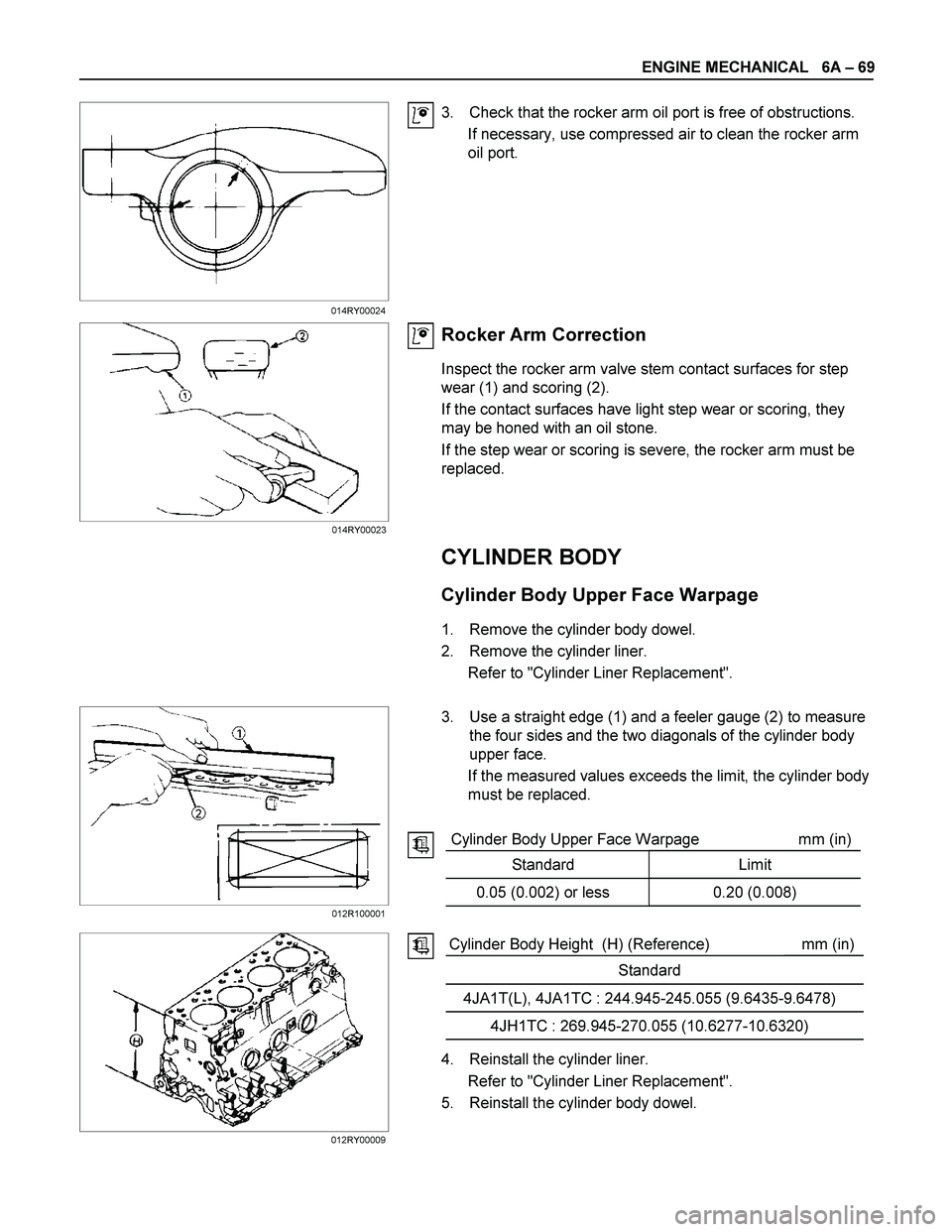
3. Check that the rocker arm oil port is free of obstructions.
If necessary, use compressed air to clean the rocker arm
oil port.
Rocker Arm Correction
Inspect the rocker arm valve stem contact surfaces for step
wear (1) and scoring (2).
If the contact surfaces have light step wear or scoring, they
may be honed with an oil stone.
If the step wear or scoring is severe, the rocker arm must be
replaced.
CYLINDER BODY
Cylinder Body Upper Face Warpage
1. Remove the cylinder body dowel.
2. Remove the cylinder liner.
Refer to "Cylinder Liner Replacement".
3. Use a straight edge (1) and a feeler gauge (2) to measure
the four sides and the two diagonals of the cylinder body
upper face.
If the measured values exceeds the limit, the cylinder body
must be replaced.
Cylinder Body Upper Face Warpage mm (in)
Standard Limit
0.05 (0.002) or less 0.20 (0.008)
Cylinder Body Height (H) (Reference) mm (in)
Standard
4JA1T(L), 4JA1TC : 244.945-245.055 (9.6435-9.6478)
4JH1TC : 269.945-270.055 (10.6277-10.6320)
4. Reinstall the cylinder liner.
Refer to "Cylinder Liner Replacement".
5. Reinstall the cylinder body dowel.
014RY00024
012R100001
012RY00009014RY00023
Page 1210 of 4264
6A – 70 ENGINE MECHANICAL
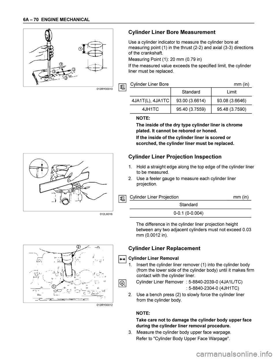
Cylinder Liner Bore Measurement
Use a cylinder indicator to measure the cylinder bore at
measuring point (1) in the thrust (2-2) and axial (3-3) directions
of the crankshaft.
Measuring Point (1): 20 mm (0.79 in)
If the measured value exceeds the specified limit, the cylinder
liner must be replaced.
Cylinder Liner Bore mm (in)
Standard Limit
4JA1T(L), 4JA1TC 93.00 (3.6614) 93.08 (3.6646)
4JH1TC 95.40 (3.7559) 95.48 (3.7590)
NOTE:
The inside of the dry type cylinder liner is chrome
plated. It cannot be rebored or honed.
If the inside of the cylinder liner is scored or
scorched, the cylinder liner must be replaced.
Cylinder Liner Projection Inspection
1. Hold a straight edge along the top edge of the cylinder liner
to be measured.
2. Use a feeler gauge to measure each cylinder liner
projection.
Cylinder Liner Projection mm (in)
Standard
0-0.1 (0-0.004)
The difference in the cylinder liner projection height
between any two adjacent cylinders must not exceed 0.03
mm (0.0012 in).
Cylinder Liner Replacement
Cylinder Liner Removal
1. Insert the cylinder liner remover (1) into the cylinder body
(from the lower side of the cylinder body) until it makes firm
contact with the cylinder liner.
Cylinder Liner Remover : 5-8840-2039-0 (4JA1L/TC)
: 5-8840-2304-0 (4JH1TC)
2. Use a bench press (2) to slowly force the cylinder liner
from the cylinder body.
NOTE:
Take care not to damage the cylinder body upper face
during the cylinder liner removal procedure.
3. Measure the cylinder body upper face warpage.
Refer to "Cylinder Body Upper Face Warpage".
012RY00010
012LX016
012RY00012
Page 1211 of 4264
ENGINE MECHANICAL 6A – 71
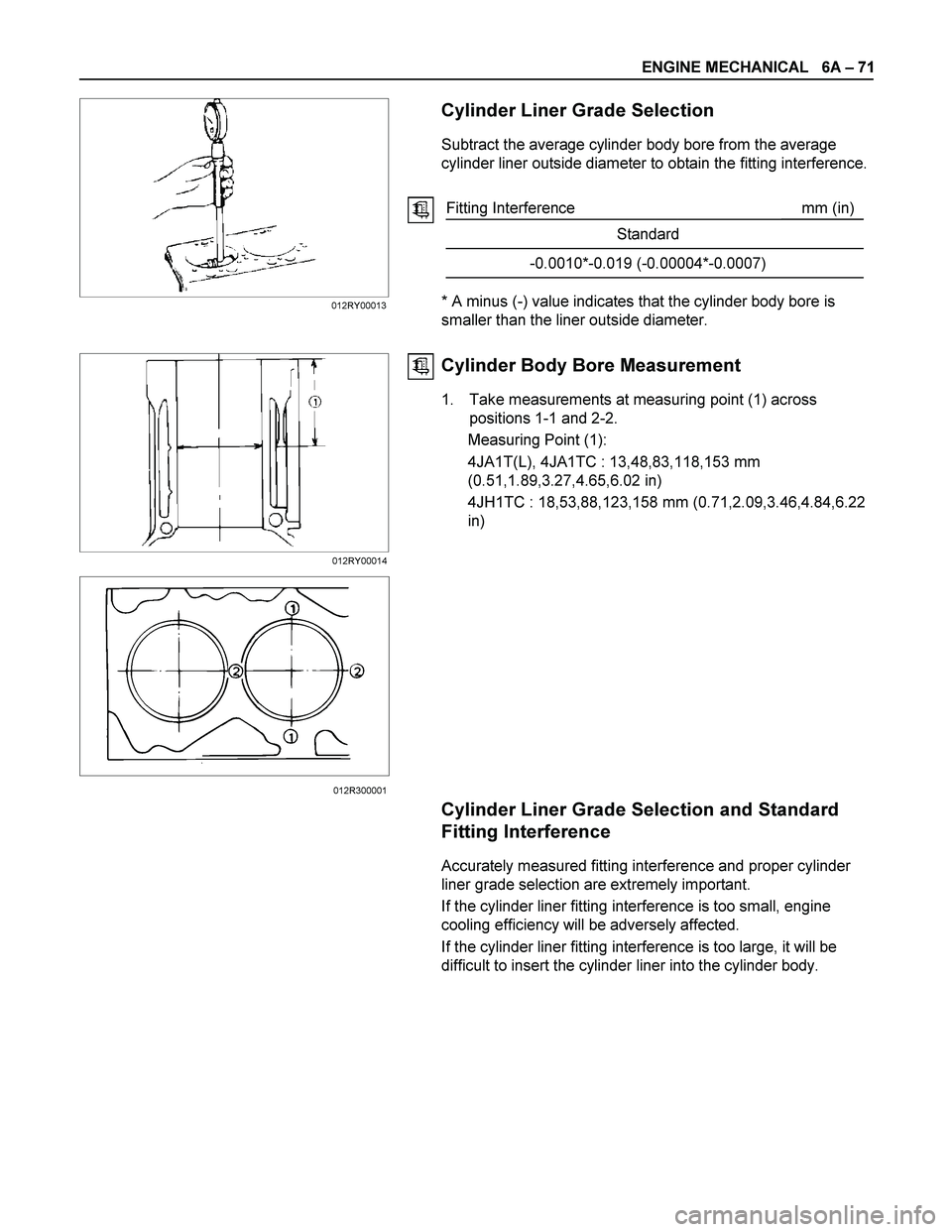
Cylinder Liner Grade Selection
Subtract the average cylinder body bore from the average
cylinder liner outside diameter to obtain the fitting interference.
Fitting Interference mm (in)
Standard
-0.0010*-0.019 (-0.00004*-0.0007)
* A minus (-) value indicates that the cylinder body bore is
smaller than the liner outside diameter.
Cylinder Body Bore Measurement
1. Take measurements at measuring point (1) across
positions 1-1 and 2-2.
Measuring Point (1):
4JA1T(L), 4JA1TC : 13,48,83,118,153 mm
(0.51,1.89,3.27,4.65,6.02 in)
4JH1TC : 18,53,88,123,158 mm (0.71,2.09,3.46,4.84,6.22
in)
Cylinder Liner Grade Selection and Standard
Fitting Interference
Accurately measured fitting interference and proper cylinder
liner grade selection are extremely important.
If the cylinder liner fitting interference is too small, engine
cooling efficiency will be adversely affected.
If the cylinder liner fitting interference is too large, it will be
difficult to insert the cylinder liner into the cylinder body.
012RY00013
012RY00014
012R300001