Page 1293 of 4264

ENGINE COOLING 6B – 13
THERMOSTAT
REMOVAL AND INSTALLATION
Read this Section carefully before performing any removal and installation procedure. This Section gives you
important points as well as the order of operation. Be sure that you understand everything in this Section before you
begin.
Removal
1. Radiator Upper Hose
1) Partially drain the engine coolant.
2) Remove the radiator upper hose.
2. Water Outlet Pipe 3) Disconnect the turbocharger-cooling pipe from outlet pipe.
4) Loosen the fixing bolt and remove the water outlet bolt.
3. Thermostat
Remove the thermostat from the thermostat housing.
Take care not to damage the thermostat.
031R300003
Inspection and Repair
Make the necessary adjustments, repairs, and part
replacements if excessive wear or damage is discovered
during inspection.
031RY00005
Operating Test of Thermostat
1. Completely submerge the thermostat in water.
2. Heat the water. Stir the water constantly to avoid direct heat being
applied to the thermostat.
3. Check the thermostat initial opening temperature.
Thermostat Initial Opening Temperature �C ( �F)
82 (180)
4. Check the thermostat full opening temperature.
Thermostat Full Opening Temperature �C ( �F)
95 (203)
Valve Lift At Fully Open Position mm (in)
9.5 (0.37)
Page 1297 of 4264

ENGINE COOLING 6B – 17
Inspection and Repair
Make the necessary adjustments, repairs, and part
replacements if excessive wear or damage is discovered
during inspection.
Radiator Cap
Measure the valve opening pressure of the pressurizing valve
with a radiator filler cap tester.
Replace the cap if the valve opening pressure is outside the
standard range.
Valve opening pressure kPa (psi) 93.3
�
�� �122.7 (13.5
�
�� �17.8)
Cap tester: 5–8840–0277–0
Adapter: 5–8840–2603–0
Check the condition of the vacuum valve in the center of the
valve seat side of the cap. If considerable rust or dirt is found,
or if the valve seat cannot be moved by hand, clean or replace
the cap.
110RS006
Valve opening vacuum kPa (psi) 1.96 �
�� � 4.91 (0.28 �
�� � 0.71)
Radiator Core
1. A bent fin may result in reduced ventilation and overheating
may occur. All bent fins must be straightened. Pay close
attention to the base of the fin when it is being straightened.
2. Remove all dust, bugs and other foreign material.
Flushing the Radiator
Thoroughly wash the inside of the radiator and the engine
coolant passages with cold water and mild detergent. Remove
all signs of scale and rust.
Cooling System Leakage Check
Use a radiator cap tester to force air into the radiator through
the filler neck at the specified pressure of 196 kPa (28.5 psi)
with a cap tester:
� Leakage from the radiator
� Leakage from the coolant pump
� Leakage from the water hoses
Page 1298 of 4264
6B – 18 ENGINE COOLING
110RS005
� Check the rubber hoses for swelling.
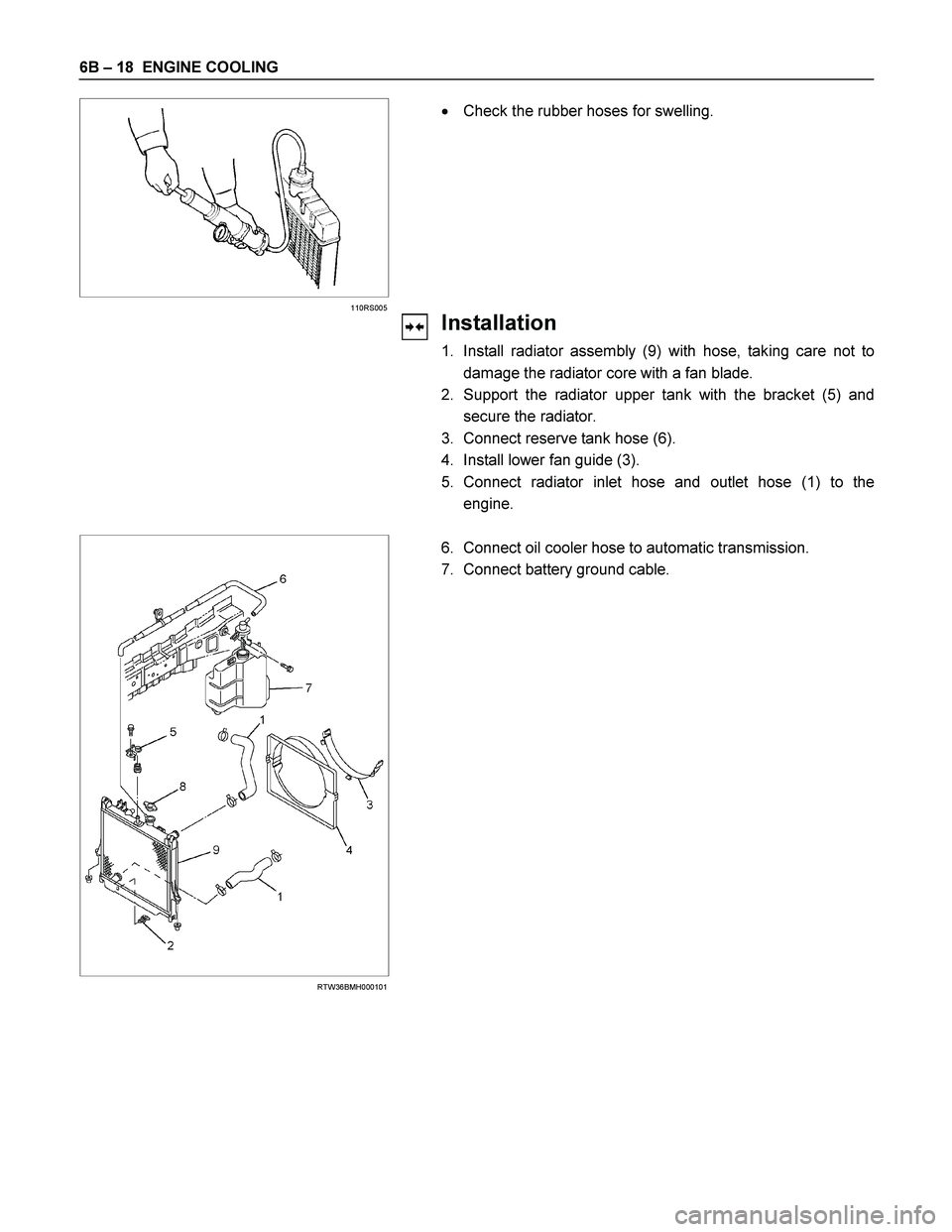
Installation
1. Install radiator assembly (9) with hose, taking care not to
damage the radiator core with a fan blade.
2. Support the radiator upper tank with the bracket (5) and
secure the radiator.
3. Connect reserve tank hose (6).
4. Install lower fan guide (3).
5. Connect radiator inlet hose and outlet hose (1) to the
engine.
RTW36BMH000101
6. Connect oil cooler hose to automatic transmission.
7. Connect battery ground cable.
Page 1303 of 4264
 4JA1TC 4JH1TC
Injection pump type
Bosch distributor
VE type Bosch distributor VP44 type
Governor type Mech")
FUEL SYSTEM 6C – 3
MAIN DATA AND SPECIFICATIONS
Description Item
4JA1T (L) 4JA1TC 4JH1TC
Injection pump type
Bosch distributor
VE type Bosch distributor VP44 type
Governor type Mechanical variable
(Half speed oil
pressure) Electrical controled
Timer type Oil pressure Electrical controled
Fuel feed pump type Vane with input shaft
Injection nozzle type Hole type
Number of injection nozzle orifices 5
Injection nozzle orifices
Inside diameter mm (in) 0.19 (0.0075) 0.17 (0.0067) 0.21 (0.0083)
19.1 (195) 19.0 (194) 19.5 (199) Injection nozzle designed operating
pressure MPa (kg/cm2) 1st
2nd 25.0 (255) 33.5 (328) 33.8 (331)
Main fuel filter type Disposable cartridge paper element
Precautions
When working on the fuel system, there are several things
to keep in mind:
Any time the fuel system is being worked on,
disconnect the negative battery cable except fo
r
those tests where battery voltage is required.
Always keep a dry chemical (Class B) fire
extinguisher near the work area.
Replace all pipes with the same pipe and fittings that
were removed.
Clean and inspect “O" rings. Replace if required.
Always relieve the line pressure before servicing any
fuel system components.
Do not attempt repairs on the fuel system until you
have read the instructions and checked the pictures
relating to that repair.
Adhere to all Notices and Cautions.
NOTE:
Injection nozzle adjustment is possible only on the 4JA1L
engine.
Page 1310 of 4264

6C – 10 FUEL SYSTEM
Removal
CAUTION: When repair to the fuel system has been
completed, start engine and check the fuel system for
loose connection or leakage. For the fuel system
diagnosis, see Section “Driveability and Emission".
1. Disconnect battery ground cable.
2. Loosen slowly the fuel filler cap.
NOTE: Be careful not to spouting out fuel because of change
the pressure in the fuel tank.
NOTE: Cover opening of the filler neck to prevent any dus
t
entering.
3. Jack up the vehicle.
4. Support underneath of the fuel tank with a lifter.
5. Remove the inner liner of the wheel house at rear left side.
6. Remove fixing bolt of the filler neck from the body.
7.
Disconnect the quick connector (3) of the fuel tube from the
fuel pipe.
NOTE: Cover the quick connector to prevent any dust entering
and fuel leakage.
NOTE: Refer to“Fuel Tube/Quick Connector Fittings” in this
section when performing any repairs.
8. Remove fixing bolt (1) of the tank band and remove the
tank band (2).
9.
Disconnect the pump and sender connector on the fuel
pump and remove the harness from weld clip on the fuel
tank.
10.
Lower the fuel tank (5).
NOTE: When lower the fuel tank from the vehicle, don’t scratch
each hose and tube by around other parts.
Installation
1. Raise the fuel tank.
NOTE: When raise the fuel tank to the vehicle, don’t scratch
each hose and tube by around other parts.
2. Connect the pump and sender connector to the fuel pump
and install the harness to weld clip on the tank.
NOTE: The connector must be certainly connected agains
t
stopper.
3. Install the tank band and fasten bolt.
Torque N·m (kg·m / lb ft)
68 (6.9 / 50)
NOTE: The anchor of the tank band must be certainly installed
to guide hole on frame.
4. Connect the quick connector of the fuel tube to the fuel pipe
and the evapo tube from evapo joint connector.
NOTE: Pull off the left checker on the fuel pipe.
NOTE: Refer to “Fuel Tube/Quick Connector Fittings” in this
section when performing any repairs.
Page 1313 of 4264

FUEL SYSTEM 6C – 13
Removal
CAUTION: When repair to the fuel system has been
completed, start engine and check the fuel system for
loose connection or leakage. For the fuel system
diagnosis, see Section “Driveability and Emission".
1. Remove fuel tank assembly (9). Refer to “Fuel Tank
Removal" in this section.
2. Disconnect the quick connector (6) of the fuel tube from fuel
gauge unit.
3. Disconnect the quick connector (10) of the evapo tube from
fuel gauge unit.
140R100035
3. Remove the retainer ring (7) from the fuel tank with the
removal tool 5-8840-2602-0.
4.
Remove slowly the fuel gauge unit (4) from the fuel tank as
no bend float arm.
NOTE: Cover opening for the fuel gauge unit on fuel tank to
prevent any dust entering.
5.
Discard fuel gauge unit seal (8) because it cannot be
reusable.
Installation
1. Clean the seal surface of the fuel tank and the fuel gauge
unit.
NOTE: If there is dust on the seal surface, it becomes cause o
f
fuel leak.
2. Install the new fuel gauge unit seal (8) to opening of the fuel
tank as along the groove.
3. Install slowly the fuel gauge unit (4) into the fuel tank as no
bend float arm.
4.
Set flange of the fuel gauge unit on fuel gauge unit seal as
mating convexity of the fuel gauge unit and reentrant of the
fuel tank.
5.
Lock slowly the retainer ring (7) to the fuel tank with the
remover tool 5-8840-2602-0.
6. Connect the quick connector (10) of the evapo tube from
fuel gauge unit.
7.
Connect the quick connector (6) of the fuel tube to to gauge
unit.
NOTE: Pull off the left ckecker of the fuel pipe.
NOTE: Refer to “Fuel Tube/Quick Connector Fittings” in this
section when performing any repairs.
Page 1316 of 4264

6C – 16 FUEL SYSTEM
140R100037
2. For removal of the quick connector, hold the quick
connector in one hand, and pull out the connector with the
other hand while pressing the square relieve button of the
connector, as illustrated.
NOTE: Do not use tools of any kind. Only use bare hands
when disconnecting the connector. Use a lubricant (light oil)
and/or push and pull the connector until the pipe is
disconnected.
140R100028
Cover the connectors that was removed with a plastic bag,
to prevent dust or rain water from entering.
140R100036
Reuse of Quick–Connector
�
Replace the port and connector if scratch, dent or crack is
found.
� Remove any dirt build up on the port when installing the
connector. Replace the connector, if there is any forms o
f
rust, dent, scratch.
�
After cleaning the port, insert it straight into the connector
until it clicks. After it clicks, try pulling at 49N (5kgf) it out to
make sure that it is not drawn and is securely locked.
Assembling Advice
By applying engine oil or light oil to the pipe, port makes pipe
assembly easier. The pipe assembly should take place
immediately after applying oil (to prevent dust from sticking to
the pipe surface – which may decrease sealing ability).
Test/Inspection After Assembling
1. Reconnect the battery negative cable.
2. Start the engine and observe the engine idle speed. The
presence of dirt in the fuel system may affect the fuel
injection system.
3. Check for fuel leakage from the connector.
Page 1350 of 4264
6D – 12 ENGINE ELECTRICAL
INSPECTION AND REPAIR
Make the necessary adjustments, repairs, and part replacement if excessive wear or damage is discovered during
inspection.
ROTOR ASSEMBLY
1. Inspect the slip ring faces for dirt and pitting. Wipe away any dirt with a clean cloth soaked in
alcohol.
2. Measure the slip ring diameter.
Slip Ring Diameter mm (in)
Standard Limit
RTW06DSH000101
31.6 (1.245) 30.6 (1.183)
If the slip ring diameter is less than the specified limit, the
slip rings must be replaced.
3. Measure the rotor coil resistance.
Rotor Coil Resistance at 20 �C (68 �F) ohms
Standard 3.8
RTW46DSH001001
RTW46DSH001101
4. Check for continuity between the slip rings and the
rotor core or shaft.
If there is continuity, the entire rotor assmbly must be
replaced.