Page 1237 of 4264
ENGINE MECHANICAL 6A – 97
Reassembly
1. Piston
2. Connecting Rod
1. Clamp the connecting rod in a vise.Take care not to
damage the connecting rod.
2. Use a pair of pliers to install the piston pin snap ring to
the piston.
RTW36ASH001801
Install the piston to the connecting rod so that the piston
head front mark (1) and the connecting rod mark (2) are
facing in the same direction.
3. Piston Pin Snap Ring
RTW36ASH001901
4. Piston Pin
1. Apply a coat of engine oil to the piston pin and the
piston pin hole.
2. Use your fingers to force the piston pin into the piston
until it makes contact with the snap ring.
5. Piston Pin Snap Ring
1. Use your fingers to force the piston pin snap ring into
the piston snap ring groove.
2. Check that the connecting rod moves smoothly on the
piston pin.
F06MV015
015R100001
Page 1238 of 4264
6A – 98 ENGINE MECHANICAL
RTW36ASH002001
6. Piston Ring
1. Use a piston ring replacer to install the three piston
rings.
Piston Ring Replacer
Install the piston rings in the order shown in the
illustration.
1. Oil ring
2. 2nd compression ring
3. 1st compression ring
NOTE:
Install the compression rings with the stamped side
facing up.
Insert the expander coil into the oil ring groove so that
there is no gap on either side of the expander coil
before installing the oil ring.
2. Apply engine oil to the piston ring surfaces.
3. Check that the piston rings rotate smoothly in the
piston ring grooves
7. Connecting Rod Bearing
Carefully wipe any oil or other foreign material from the
connecting rod bearing back face and the connecting rod
bearing fitting surface.
015R100006
Page 1245 of 4264
ENGINE MECHANICAL 6A – 105
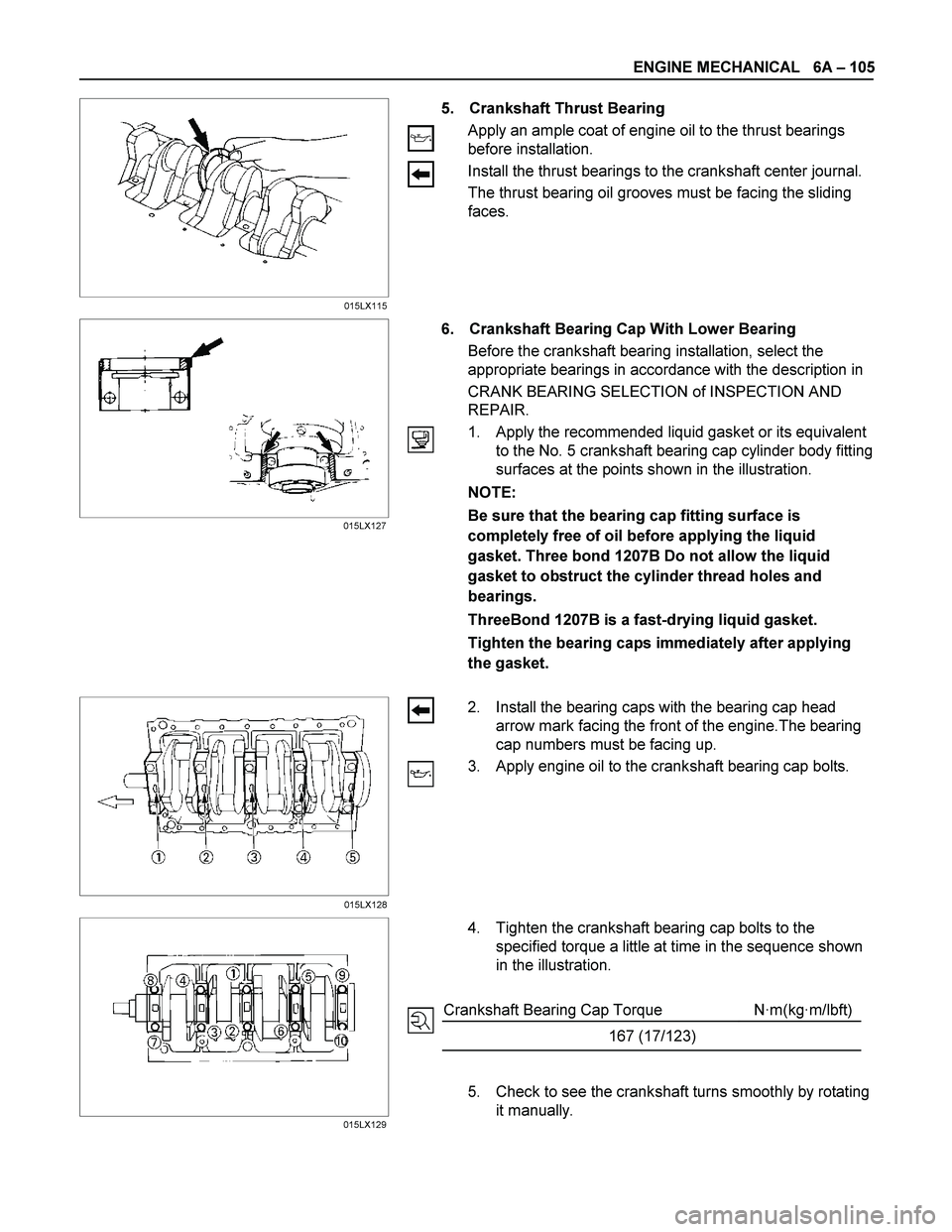
5. Crankshaft Thrust Bearing
Apply an ample coat of engine oil to the thrust bearings
before installation.
Install the thrust bearings to the crankshaft center journal.
The thrust bearing oil grooves must be facing the sliding
faces.
6. Crankshaft Bearing Cap With Lower Bearing
Before the crankshaft bearing installation, select the
appropriate bearings in accordance with the description in
CRANK BEARING SELECTION of INSPECTION AND
REPAIR.
1. Apply the recommended liquid gasket or its equivalent
to the No. 5 crankshaft bearing cap cylinder body fitting
surfaces at the points shown in the illustration.
NOTE:
Be sure that the bearing cap fitting surface is
completely free of oil before applying the liquid
gasket. Three bond 1207B Do not allow the liquid
gasket to obstruct the cylinder thread holes and
bearings.
ThreeBond 1207B is a fast-drying liquid gasket.
Tighten the bearing caps immediately after applying
the gasket.
2. Install the bearing caps with the bearing cap head
arrow mark facing the front of the engine.The bearing
cap numbers must be facing up.
3. Apply engine oil to the crankshaft bearing cap bolts.
4. Tighten the crankshaft bearing cap bolts to the
specified torque a little at time in the sequence shown
in the illustration.
Crankshaft Bearing Cap Torque N·m(kg·m/lbft)
167 (17/123)
5. Check to see the crankshaft turns smoothly by rotating
it manually.
015LX115
015LX127
015LX128
015LX129
Page 1248 of 4264
6A – 108 ENGINE MECHANICAL
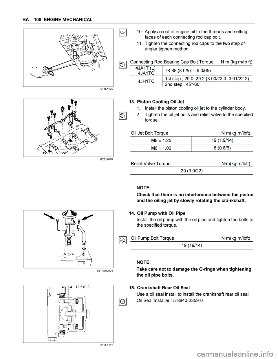
10. Apply a coat of engine oil to the threads and setting
faces of each connecting rod cap bolt.
11. Tighten the connecting rod caps to the two step of
anglar tigthen method.
Connecting Rod Bearing Cap Bolt Torque N·m (kg·m/Ib ft)
4JA1T (L),
4JA1TC 78-88 (8.0/57 – 9.0/65)
1st step ; 29.0–29.2 (3.00/22.0–3.01/22.2)4JH1TC
2nd step ; 45�-60�
13. Piston Cooling Oil Jet
1. Install the piston cooling oil jet to the cylinder body.
2. Tighten the oil jet bolts and relief valve to the specified
torque.
Oil Jet Bolt Torque N·m(kg·m/lbft)
M8 � 1.25 19 (1.9/14)
M6 � 1.00 8 (0.8/6)
Relief Valve Torque N·m(kg·m/lbft)
29 (3.0/22)
NOTE:
Check that there is no interference between the piston
and the oiling jet by slowly rotating the crankshaft.
14. Oil Pump with Oil Pipe
Install the oil pump with the oil pipe and tighten the bolts to
the specified torque.
Oil Pump Bolt Torque N·m(kg·m/lbft)
19 (19/14)
NOTE:
Take care not to damage the O-rings when tightening
the oil pipe bolts.
15. Crankshaft Rear Oil Seal
Use a oil seal install to install the crankshaft rear oil seal.
Oil Seal Installer : 5-8840-2359-0
015LX130
015LX112 052LX010
051R100004
Page 1257 of 4264
ENGINE MECHANICAL 6A – 117
RTW46ASH001201
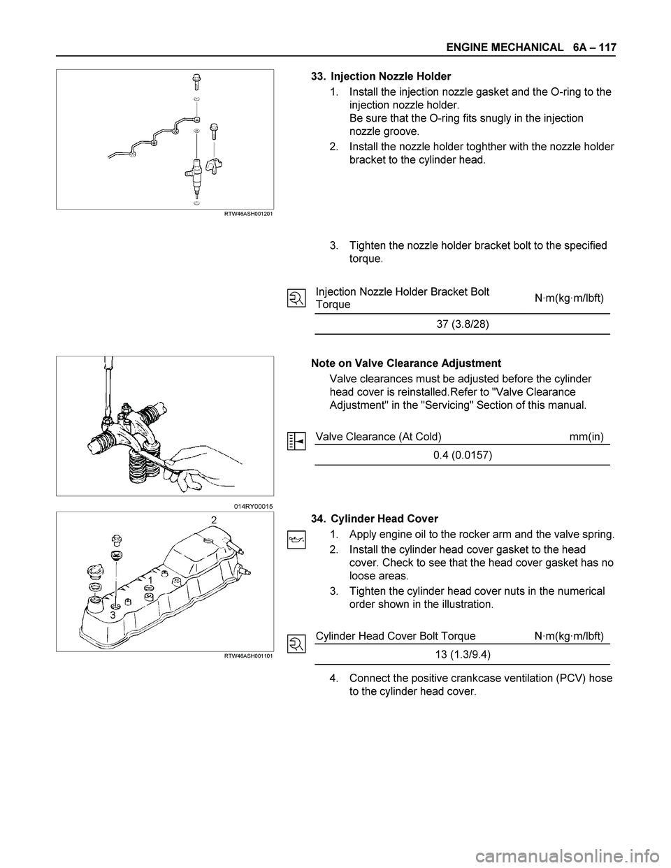
33. Injection Nozzle Holder
1. Install the injection nozzle gasket and the O-ring to the
injection nozzle holder.
Be sure that the O-ring fits snugly in the injection
nozzle groove.
2. Install the nozzle holder toghther with the nozzle holder
bracket to the cylinder head.
3. Tighten the nozzle holder bracket bolt to the specified
torque.
Injection Nozzle Holder Bracket Bolt
Torque N·m(kg·m/lbft)
37 (3.8/28)
Note on Valve Clearance Adjustment
Valve clearances must be adjusted before the cylinder
head cover is reinstalled.Refer to "Valve Clearance
Adjustment" in the "Servicing" Section of this manual.
Valve Clearance (At Cold) mm(in)
0.4 (0.0157)
RTW46ASH001101
34. Cylinder Head Cover
1. Apply engine oil to the rocker arm and the valve spring.
2. Install the cylinder head cover gasket to the head
cover. Check to see that the head cover gasket has no
loose areas.
3. Tighten the cylinder head cover nuts in the numerical
order shown in the illustration.
Cylinder Head Cover Bolt Torque N·m(kg·m/lbft)
13 (1.3/9.4)
4. Connect the positive crankcase ventilation (PCV) hose
to the cylinder head cover.
014RY00015
Page 1288 of 4264
6B – 8 ENGINE COOLING
Draining and Refilling Cooling System
Before draining the cooling system, inspect the system and
perform any necessary service to ensure that it is clean, does
not leak and is in proper working order. The engine coolan
t
(EC) level should be between the “MIN" and “MAX" lines o
f
reserve tank when the engine is cold. If low, check for leakage
and add EC up to the “MAX" line.
There should not be any excessive deposit of rust or scales
around the radiator cap or radiator filler hole, and the EC
should also be free from oil.
Replace the EC if excessively dirty.
P1010064
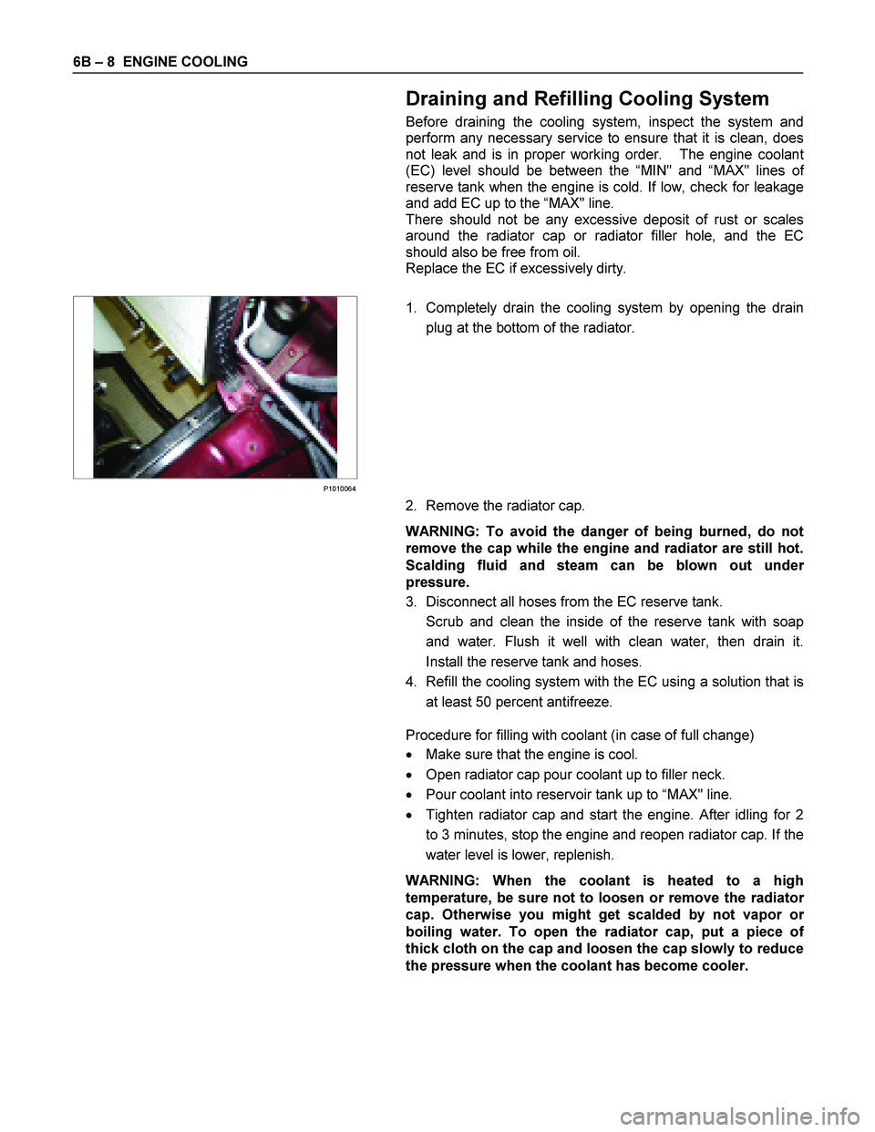
1. Completely drain the cooling system by opening the drain
plug at the bottom of the radiator.
2. Remove the radiator cap.
WARNING: To avoid the danger of being burned, do not
remove the cap while the engine and radiator are still hot.
Scalding fluid and steam can be blown out unde
r
pressure.
3. Disconnect all hoses from the EC reserve tank.
Scrub and clean the inside of the reserve tank with soap and water. Flush it well with clean water, then drain it.
Install the reserve tank and hoses.
4. Refill the cooling system with the EC using a solution that is at least 50 percent antifreeze.
Procedure for filling with coolant (in case of full change)
� Make sure that the engine is cool.
� Open radiator cap pour coolant up to filler neck.
� Pour coolant into reservoir tank up to “MAX" line.
� Tighten radiator cap and start the engine. After idling for 2
to 3 minutes, stop the engine and reopen radiator cap. If the
water level is lower, replenish.
WARNING: When the coolant is heated to a high
temperature, be sure not to loosen or remove the radiato
r
cap. Otherwise you might get scalded by not vapor or
boiling water. To open the radiator cap, put a piece of
thick cloth on the cap and loosen the cap slowly to reduce
the pressure when the coolant has become cooler.
Page 1289 of 4264
ENGINE COOLING 6B – 9
� After tightening radiator cap, warm up the engine at about
2000 rpm. Set heater adjustment to the highest temperature
position, and let the coolant circulate also into heater wate
r
system.
� Check to see the thermostat has opened through the
needle position of water thermometer, conduct a 5–minute
idling again and stop the engine.
� When the engine has been cooled, check filler neck fo
r
water level and replenish if required. Should extreme
shortage of coolant is found, check the cooling system and
reservoir tank hose for leakage.
� Pour coolant into the reservoir tank up to “MAX" line.
Page 1291 of 4264
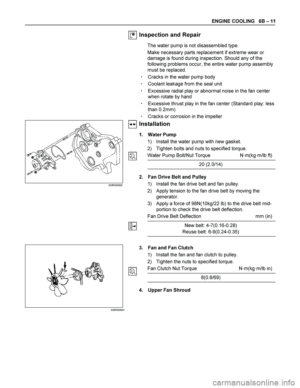
ENGINE COOLING 6B – 11
Inspection and Repair
The water pump is not disassembled type.
Make necessary parts replacement if extreme wear or
damage is found during inspection. Should any of the
following problems occur, the entire water pump assembly
must be replaced.
��Cracks in the water pump body
��Coolant leakage from the seal unit
��Excessive radial play or abnormal noise in the fan center
when rotate by hand
��Excessive thrust play in the fan center (Standard play: less
than 0.2mm)
��Cracks or corrosion in the impeller
Installation
1. Water Pump
1) Install the water pump with new gasket.
2) Tighten bolts and nuts to specified torque.
Water Pump Bolt/Nut Torque N·m(kg·m/lb ft)
20 (2.0/14)
2. Fan Drive Belt and Pulley
1) Install the fan drive belt and fan pulley.
2) Apply tension to the fan drive belt by moving the
generator.
3) Apply a force of 98N(10kg/22 lb) to the drive belt mid-
portion to check the drive belt deflection.
Fan Drive Belt Deflection mm (in)
New belt: 4-7(0.16-0.28)
Reuse belt: 6-9(0.24-0.35)
030R300002
030R300001
3. Fan and Fan Clutch
1) Install the fan and fan clutch to pulley.
2) Tighten the nuts to specified torque.
Fan Clutch Nut Torque N·m(kg·m/lb in)
8(0.8/69)
4. Upper Fan Shroud