Page 1181 of 4264
ENGINE MECHANICAL 6A – 41
Coolant Replenishment
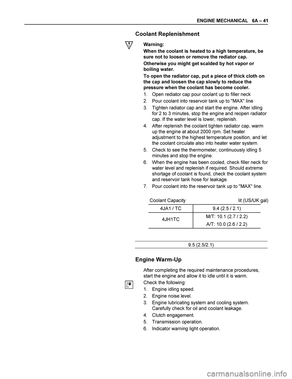
Warning:
When the coolant is heated to a high temperature, be
sure not to loosen or remove the rediator cap.
Otherwise you might get scalded by hot vapor or
boiling water.
To open the radiator cap, put a piece of thick cloth on
the cap and loosen the cap slowly to reduce the
pressure when the coolant has become cooler.
1. Open rediator cap pour coolant up to filler neck
2. Pour coolant into reservoir tank up to "MAX" line
3. Tighten radiator cap and start the engine. After idling
for 2 to 3 minutes, stop the engine and reopen radiator
cap. If the water level is lower, replenish.
4. After replenish the coolant tighten radiator cap, warm
up the engine at about 2000 rpm. Set heater
adjustment to the highest temperature position, and let
the coolant circulate also into heater water system.
5. Check to see the thermometer, continuously idling 5
minutes and stop the engine.
6. When the engine has been cooled, check filler neck for
water level and replenish if required. Should extreme
shortage of coolant is found, check the coolant system
and reservoir tank hose for leakage.
7. Pour coolant into the reservoir tank up to "MAX" line.
Coolant Capacity lit (US/UK gal)
4JA1 / TC 9.4 (2.5 / 2.1)
4JH1TC M/T: 10.1 (2.7 / 2.2)
A/T: 10.0 (2.6 / 2.2)
9.5 (2.5/2.1)
Engine Warm-Up
After completing the required maintenance procedures,
start the engine and allow it to idle until it is warm.
Check the following:
1. Engine idling speed.
2. Engine noise level.
3. Engine lubricating system and cooling system.
Carefully check for oil and coolant leakage.
4. Clutch engagement.
5. Transmission operation.
6. Indicator warning light operation.
Page 1191 of 4264
ENGINE MECHANICAL 6A – 51
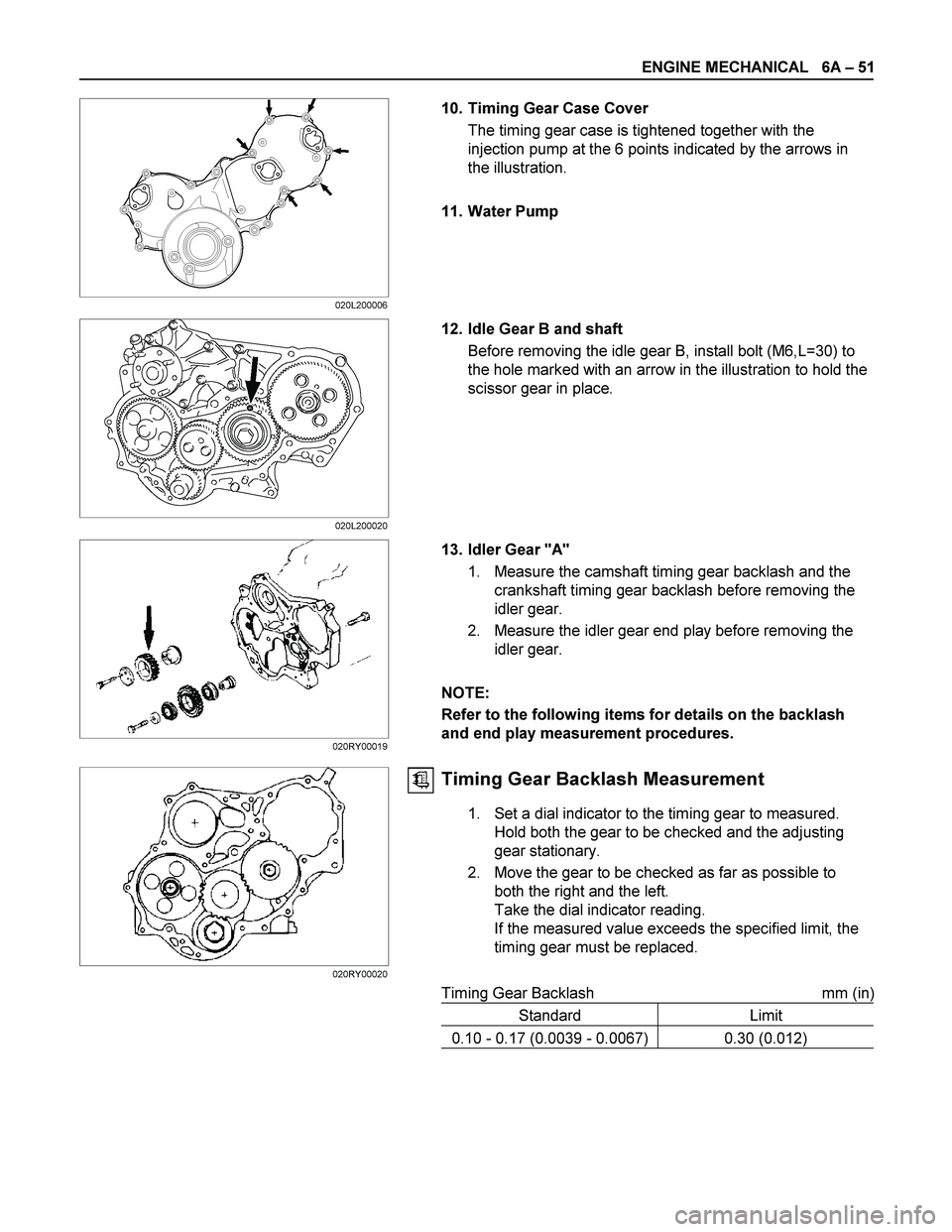
10. Timing Gear Case Cover
The timing gear case is tightened together with the
injection pump at the 6 points indicated by the arrows in
the illustration.
11. Water Pump
12. Idle Gear B and shaft
Before removing the idle gear B, install bolt (M6,L=30) to
the hole marked with an arrow in the illustration to hold the
scissor gear in place.
13. Idler Gear "A"
1. Measure the camshaft timing gear backlash and the
crankshaft timing gear backlash before removing the
idler gear.
2. Measure the idler gear end play before removing the
idler gear.
NOTE:
Refer to the following items for details on the backlash
and end play measurement procedures.
Timing Gear Backlash Measurement
1. Set a dial indicator to the timing gear to measured.
Hold both the gear to be checked and the adjusting
gear stationary.
2. Move the gear to be checked as far as possible to
both the right and the left.
Take the dial indicator reading.
If the measured value exceeds the specified limit, the
timing gear must be replaced.
Timing Gear Backlash mm (in)
Standard Limit
0.10 - 0.17 (0.0039 - 0.0067) 0.30 (0.012)
020L200006
020L200020
020RY00019
020RY00020
Page 1205 of 4264
ENGINE MECHANICAL 6A – 65
Valve Contact Width
1. Check the valve contact faces for roughness and
unevenness. Make smooth the valve contact surfaces.
2. Measure the valve contact width.
If the measured value exceeds the specified limit, the valve
seat insert must be replaced.
Valve Contact Width mm (in)
Standard Limit
Intake 1.7 (0.067) 2.2 (0.087)
Exhaust 2.0 (0.079) 2.5 (0.078)
Valve Seat Insert Replacement
Valve Seat Insert Removal
1. Arc weld the entire inside circumference (1) of the valve
seat insert (2).
2. Allow the valve seat insert to cool for a few minutes.
This will invite contraction and make removal of the valve
seat insert easier.
3. Use a screwdriver (3) to pry the valve seat insert free.
Take care not to damage the cylinder head (4).
4. Carefully remove carbon and other foreign material from
the cylinder head insert bore.
014RY00027
011LX039
Page 1206 of 4264
6A – 66 ENGINE MECHANICAL
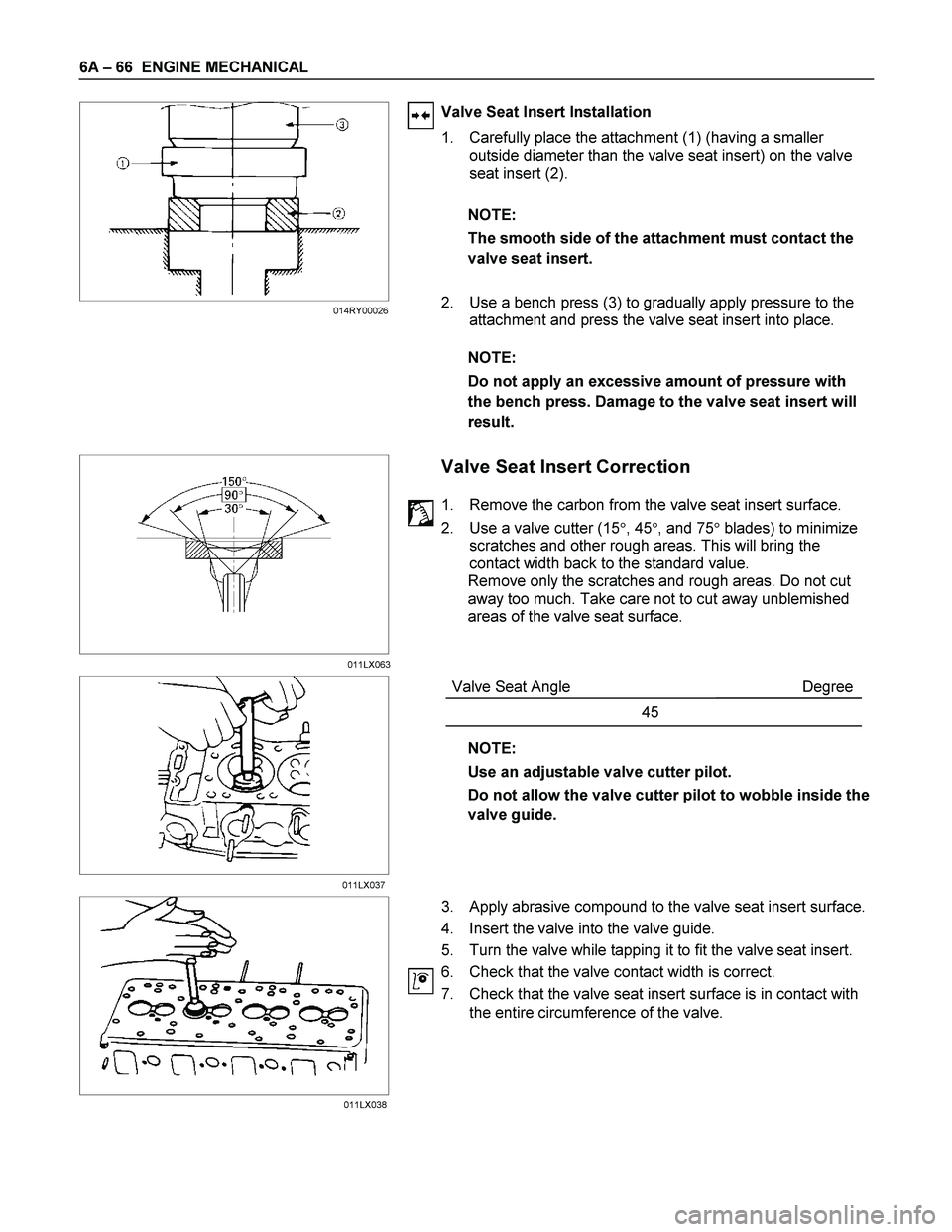
Valve Seat Insert Installation
1. Carefully place the attachment (1) (having a smaller
outside diameter than the valve seat insert) on the valve
seat insert (2).
NOTE:
The smooth side of the attachment must contact the
valve seat insert.
2. Use a bench press (3) to gradually apply pressure to the
attachment and press the valve seat insert into place.
NOTE:
Do not apply an excessive amount of pressure with
the bench press. Damage to the valve seat insert will
result.
Valve Seat Insert Correction
1. Remove the carbon from the valve seat insert surface.
2. Use a valve cutter (15�, 45�, and 75� blades) to minimize
scratches and other rough areas. This will bring the
contact width back to the standard value.
Remove only the scratches and rough areas. Do not cut
away too much. Take care not to cut away unblemished
areas of the valve seat surface.
Valve Seat Angle Degree
45
NOTE:
Use an adjustable valve cutter pilot.
Do not allow the valve cutter pilot to wobble inside the
valve guide.
3. Apply abrasive compound to the valve seat insert surface.
4. Insert the valve into the valve guide.
5. Turn the valve while tapping it to fit the valve seat insert.
6. Check that the valve contact width is correct.
7. Check that the valve seat insert surface is in contact with
the entire circumference of the valve.
011LX063 014RY00026
011LX037
011LX038
Page 1209 of 4264
ENGINE MECHANICAL 6A – 69
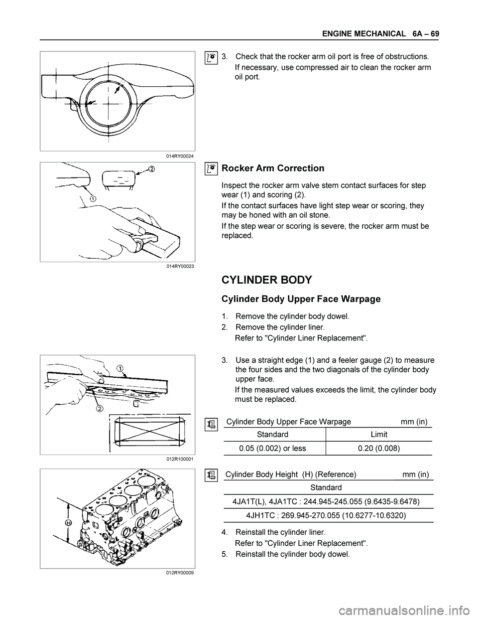
3. Check that the rocker arm oil port is free of obstructions.
If necessary, use compressed air to clean the rocker arm
oil port.
Rocker Arm Correction
Inspect the rocker arm valve stem contact surfaces for step
wear (1) and scoring (2).
If the contact surfaces have light step wear or scoring, they
may be honed with an oil stone.
If the step wear or scoring is severe, the rocker arm must be
replaced.
CYLINDER BODY
Cylinder Body Upper Face Warpage
1. Remove the cylinder body dowel.
2. Remove the cylinder liner.
Refer to "Cylinder Liner Replacement".
3. Use a straight edge (1) and a feeler gauge (2) to measure
the four sides and the two diagonals of the cylinder body
upper face.
If the measured values exceeds the limit, the cylinder body
must be replaced.
Cylinder Body Upper Face Warpage mm (in)
Standard Limit
0.05 (0.002) or less 0.20 (0.008)
Cylinder Body Height (H) (Reference) mm (in)
Standard
4JA1T(L), 4JA1TC : 244.945-245.055 (9.6435-9.6478)
4JH1TC : 269.945-270.055 (10.6277-10.6320)
4. Reinstall the cylinder liner.
Refer to "Cylinder Liner Replacement".
5. Reinstall the cylinder body dowel.
014RY00024
012R100001
012RY00009014RY00023
Page 1213 of 4264
ENGINE MECHANICAL 6A – 73
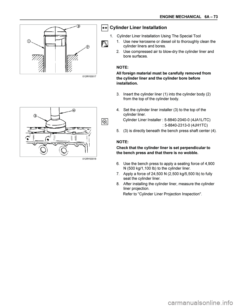
Cylinder Liner Installation
1. Cylinder Liner Installation Using The Special Tool
1. Use new kerosene or diesel oil to thoroughly clean the
cylinder liners and bores.
2. Use compressed air to blow-dry the cylinder liner and
bore surfaces.
NOTE:
All foreign material must be carefully removed from
the cylinder liner and the cylinder bore before
installation.
3. Insert the cylinder liner (1) into the cylinder body (2)
from the top of the cylinder body.
4. Set the cylinder liner installer (3) to the top of the
cylinder liner.
Cylinder Liner Installer : 5-8840-2040-0 (4JA1L/TC)
: 5-8840-2313-0 (4JH1TC)
5. (3) is directly beneath the bench press shaft center (4).
NOTE:
Check that the cylinder liner is set perpendicular to
the bench press and that there is no wobble.
6. Use the bench press to apply a seating force of 4,900
N (500 kg/1,100 Ib) to the cylinder liner.
7. Apply a force of 24,500 N (2,500 kg/5,500 Ib) to fully
seat the cylinder liner.
8. After installing the cylinder liner, measure the cylinder
liner projection.
Refer to "Cylinder Liner Projection Inspection".
012RY00017
012RY00018
Page 1225 of 4264
ENGINE MECHANICAL 6A – 85
CRANKSHAFT PILOT BEARING
Check the crankshaft pilot bearing for excessive wear and
damage and replace it if necessary.
Crankshaft Pilot Bearing Replacement
Crankshaft Pilot Bearing Removal
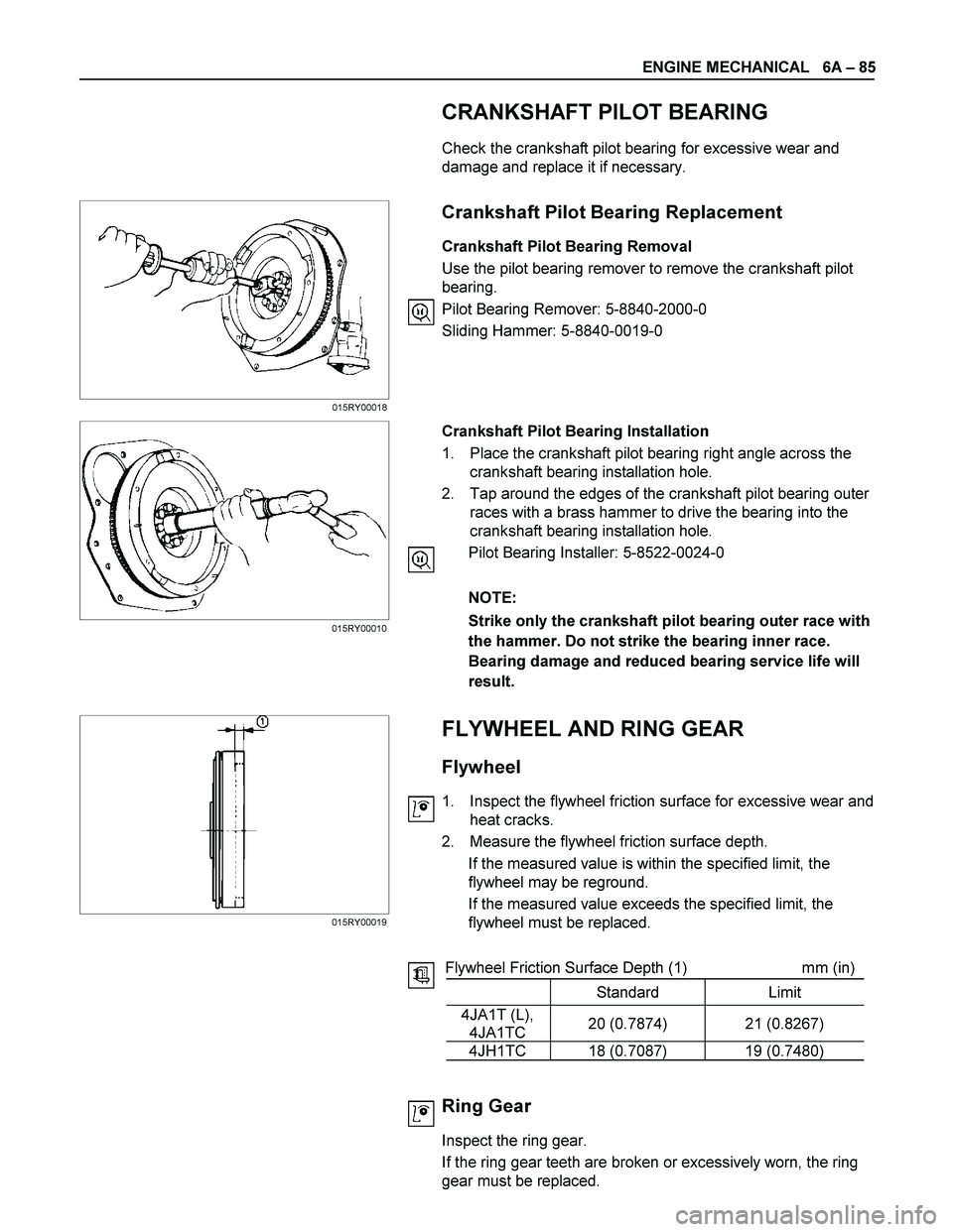
Use the pilot bearing remover to remove the crankshaft pilot
bearing.
Pilot Bearing Remover: 5-8840-2000-0
Sliding Hammer: 5-8840-0019-0
Crankshaft Pilot Bearing Installation
1. Place the crankshaft pilot bearing right angle across the
crankshaft bearing installation hole.
2. Tap around the edges of the crankshaft pilot bearing outer
races with a brass hammer to drive the bearing into the
crankshaft bearing installation hole.
Pilot Bearing Installer: 5-8522-0024-0
NOTE:
Strike only the crankshaft pilot bearing outer race with
the hammer. Do not strike the bearing inner race.
Bearing damage and reduced bearing service life will
result.
FLYWHEEL AND RING GEAR
Flywheel
1. Inspect the flywheel friction surface for excessive wear and
heat cracks.
2. Measure the flywheel friction surface depth.
If the measured value is within the specified limit, the
flywheel may be reground.
If the measured value exceeds the specified limit, the
flywheel must be replaced.
Flywheel Friction Surface Depth (1) mm (in)
Standard Limit
4JA1T (L),
4JA1TC 20 (0.7874) 21 (0.8267)
4JH1TC 18 (0.7087) 19 (0.7480)
Ring Gear
Inspect the ring gear.
If the ring gear teeth are broken or excessively worn, the ring
gear must be replaced.
015RY00010
015RY00019015RY00018
Page 1232 of 4264
6A – 92 ENGINE MECHANICAL
Oil Seal Installation
Use the special tool to install the front oil seal.
Front Oil Seal Installer: 5-8840-2361-0
1. With the oil seal attached to the sleeve, insert it into the
front end section of the crankshaft.
2. With the oil seal end section attached securely to the
crankshaft, tighten up the center bolt until the sleeve hits
the front end reference plane of the crankshaft securely.
3. Remove the sleeve.
4. With the seal pressed in, check the dimension of the oil
seal section.
Standard Dimension = 1.0 � 0.03mm
NOTE:
Install the oil seal after assembling the timing pulley
housing. The oil seal lip section is applied with oil.
Take notice of the press-in direction of the oil seal.
020R300005