Page 2774 of 3371
POWER STEERING GEAR AND LINKAGE
PS-23
C
D
E
F
H
I
J
K
L
MA
B
PS
Revision: August 20072004 QX56
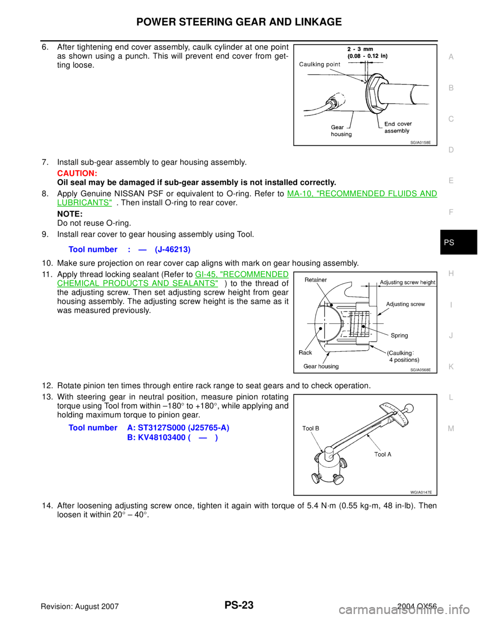
6. After tightening end cover assembly, caulk cylinder at one point
as shown using a punch. This will prevent end cover from get-
ting loose.
7. Install sub-gear assembly to gear housing assembly.
CAUTION:
Oil seal may be damaged if sub-gear assembly is not installed correctly.
8. Apply Genuine NISSAN PSF or equivalent to O-ring. Refer to MA-10, "
RECOMMENDED FLUIDS AND
LUBRICANTS" . Then install O-ring to rear cover.
NOTE:
Do not reuse O-ring.
9. Install rear cover to gear housing assembly using Tool.
10. Make sure projection on rear cover cap aligns with mark on gear housing assembly.
11. Apply thread locking sealant (Refer to GI-45, "
RECOMMENDED
CHEMICAL PRODUCTS AND SEALANTS" ) to the thread of
the adjusting screw. Then set adjusting screw height from gear
housing assembly. The adjusting screw height is the same as it
was measured previously.
12. Rotate pinion ten times through entire rack range to seat gears and to check operation.
13. With steering gear in neutral position, measure pinion rotating
torque using Tool from within –180° to +180°, while applying and
holding maximum torque to pinion gear.
14. After loosening adjusting screw once, tighten it again with torque of 5.4 N·m (0.55 kg-m, 48 in-lb). Then
loosen it within 20° – 40°.
SGIA0158E
Tool number : — (J-46213)
SGIA0568E
Tool number A: ST3127S000 (J25765-A)
B: KV48103400 ( — )
WGIA0147E
Page 2777 of 3371
PS-26
POWER STEERING OIL PUMP
Revision: August 20072004 QX56
POWER STEERING OIL PUMPPFP:49110
On-Vehicle Inspection and ServiceEGS000MW
CHECKING RELIEF OIL PRESSURE
CAUTION:
Before starting work, confirm belt tension is proper.
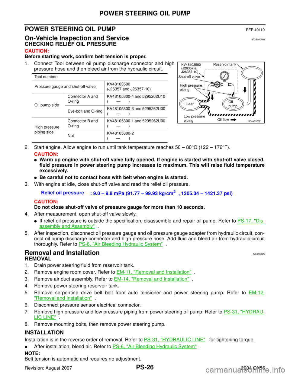
1. Connect Tool between oil pump discharge connector and high
pressure hose and then bleed air from the hydraulic circuit.
2. Start engine. Allow engine to run until tank temperature reaches 50 – 80°C (122 – 176°F).
CAUTION:
�Warm up engine with shut-off valve fully opened. If engine is started with shut-off valve closed,
fluid pressure in power steering pump increases to maximum. This will raise fluid temperature
excessively.
�Be careful not to contact hose with belt when engine is started.
3. With engine at idle, close shut-off valve and read the relief oil pressure.
CAUTION:
Do not close shut-off valve of pressure gauge for more than 10 seconds.
4. After measurement, open shut-off valve slowly.
�If relief oil pressure is outside the specification, disassemble and repair oil pump. Refer to PS-17, "Dis-
assembly and Assembly" .
5. After inspection, disconnect oil pressure gauge and oil pressure gauge adapter from hydraulic circuit, con-
nect oil pump discharge connector and high pressure hose. Add fluid and bleed air from hydraulic circuit
thoroughly. Refer to PS-6, "
Air Bleeding Hydraulic System" .
Removal and InstallationEG S0 0 0MX
REMOVAL
1. Drain power steering fluid from reservoir tank.
2. Remove engine room cover. Refer to EM-11, "
Removal and Installation" .
3. Remove air duct assembly. Refer to EM-14, "
Removal and Installation" .
4. Remove power steering reservoir tank.
5. Remove serpentine drive belt belt from auto tensioner and power steering pump. Refer to EM-12,
"Removal and Installation" .
6. Disconnect pressure sensor electrical connector.
7. Remove high pressure and low pressure piping from power steering oil pump. Refer to PS-31, "
HYDRAU-
LIC LINE" .
8. Remove mounting bolts, then remove power steering pump.
INSTALLATION
Installation is in the reverse order of removal. Refer to PS-31, "HYDRAULIC LINE" for tightening torque.
�After installation, bleed air. Refer to PS-6, "Air Bleeding Hydraulic System" .
NOTE:
Belt tension is automatic and requires no adjustment.
Tool number:
Pressure gauge and shut-off valveKV48103500
(J26357 and J26357-10)
Oil pump sideConnector A and
O-ringKV48105300-4 and 5295262U10
(—)
Eye-bolt and O-ringKV48105300-3 and 5295262U00
(—)
High pressure
piping sideConnector B and
O-ringKV48105300-1 and 5295262U00
(—)
NutKV48105300-2
( — )
Relief oil pressure
: 9.0 – 9.8 mPa (91.77 – 99.93 kg/cm2 , 1305.34 – 1421.37 psi)
SGIA0570E
Page 2833 of 3371
RFD-2
PREPARATION
Revision: August 20072004 QX56
PREPARATIONPFP:00002
Special Service ToolsEDS0 02 JH
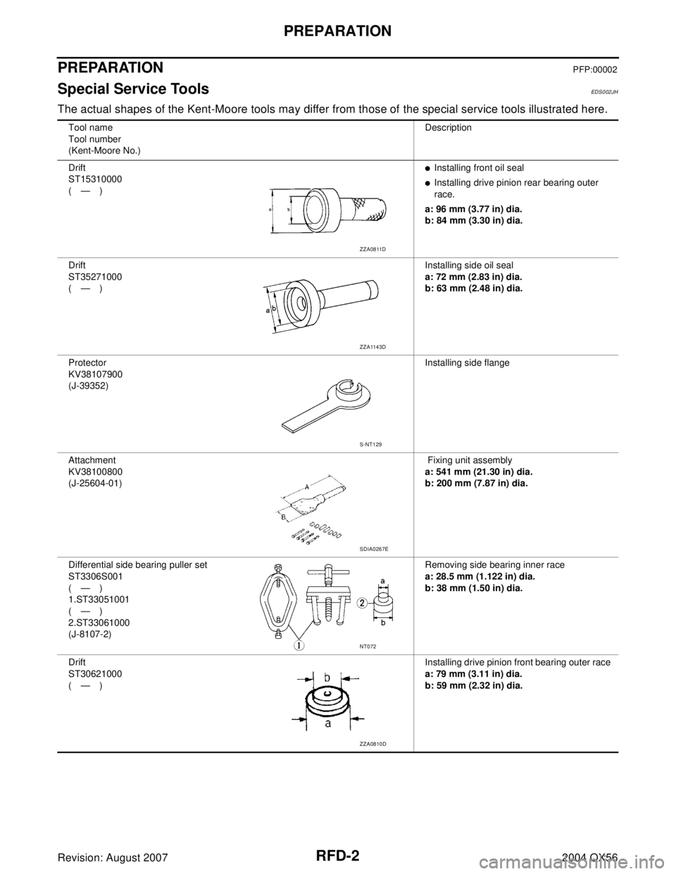
The actual shapes of the Kent-Moore tools may differ from those of the special service tools illustrated here.
Tool name
Tool number
(Kent-Moore No.)Description
Drift
ST15310000
(—)
�Installing front oil seal
�Installing drive pinion rear bearing outer
race.
a: 96 mm (3.77 in) dia.
b: 84 mm (3.30 in) dia.
Drift
ST35271000
(—)Installing side oil seal
a: 72 mm (2.83 in) dia.
b: 63 mm (2.48 in) dia.
Protector
KV38107900
(J-39352)Installing side flange
Attachment
KV38100800
(J-25604-01) Fixing unit assembly
a: 541 mm (21.30 in) dia.
b: 200 mm (7.87 in) dia.
Differential side bearing puller set
ST3306S001
(—)
1.ST33051001
(—)
2.ST33061000
(J-8107-2)Removing side bearing inner race
a: 28.5 mm (1.122 in) dia.
b: 38 mm (1.50 in) dia.
Drift
ST30621000
(—)Installing drive pinion front bearing outer race
a: 79 mm (3.11 in) dia.
b: 59 mm (2.32 in) dia.
ZZA0811D
ZZA1143D
S-NT129
SDIA0267E
NT072
ZZA0810D
Page 2835 of 3371
RFD-4
PREPARATION
Revision: August 20072004 QX56
Commercial Service ToolsEDS002JI
Side bearing outer race puller
ST33290001
(J-34286)Removing front oil seal
Drift
ST33081000
(—)Installing side bearing
a: 43 mm (1.69 in) dia.
b: 33.5 mm (1.31 in) dia.
Bearing puller
ST30021000
(—)Removing drive pinion rear bearing inner
race
Drift
ST30022000
(—)Installing drive pinion rear bearing inner race
a: 110 mm (4.33 in) dia.
b: 46 mm (1.81 in) dia. Tool name
Tool number
(Kent-Moore No.)Description
ZZA0601D
ZZA0810D
ZZA0700D
ZZA0920D
Tool nameDescription
Power toolRemoving bolts and nuts
PBIC0190E
Page 2837 of 3371
RFD-6
FRONT OIL SEAL
Revision: August 20072004 QX56
FRONT OIL SEALPFP:38189
Removal and InstallationEDS002JK
REMOVAL
1. Remove the drive shaft inside flange bolts to disconnect the rear drive shafts from the rear final drive.
Support the rear drive shafts using suitable wire.
NOTE:
Disconnecting the rear drive shafts is necessary to measure the total preload accurately.
2. Remove the rear propeller shaft. Refer to PR-8, "
Removal and Installation" .
CAUTION:
Do not damage the propeller shaft tube.
3. Check the total preload. Refer to RFD-12, "
TOTAL PRELOAD" .
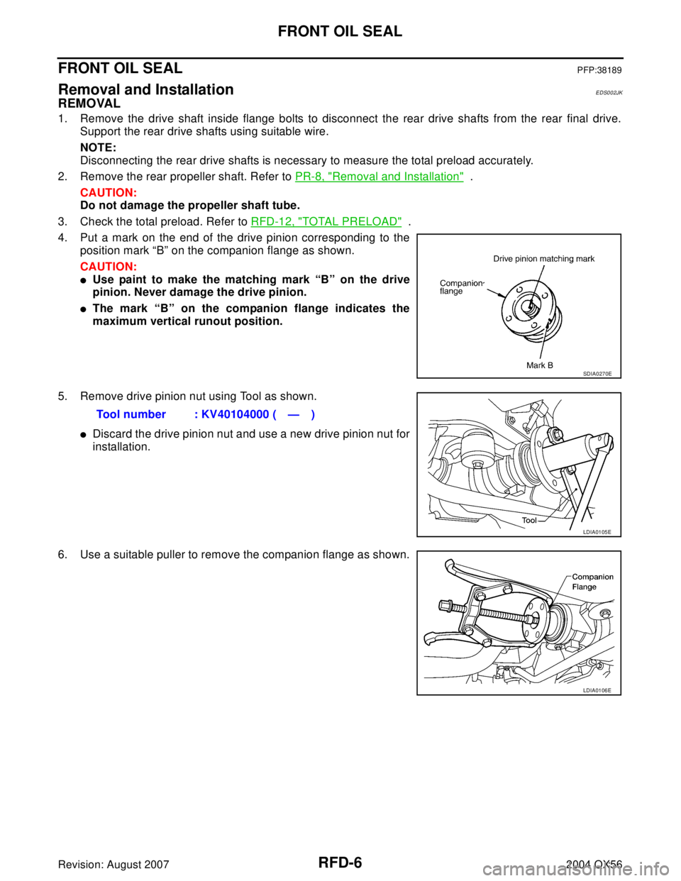
4. Put a mark on the end of the drive pinion corresponding to the
position mark “B” on the companion flange as shown.
CAUTION:
�Use paint to make the matching mark “B” on the drive
pinion. Never damage the drive pinion.
�The mark “B” on the companion flange indicates the
maximum vertical runout position.
5. Remove drive pinion nut using Tool as shown.
�Discard the drive pinion nut and use a new drive pinion nut for
installation.
6. Use a suitable puller to remove the companion flange as shown.
SDIA0270E
Tool number : KV40104000 ( — )
LDIA0105E
LDIA0106E
Page 2838 of 3371
FRONT OIL SEAL
RFD-7
C
E
F
G
H
I
J
K
L
MA
B
RFD
Revision: August 20072004 QX56
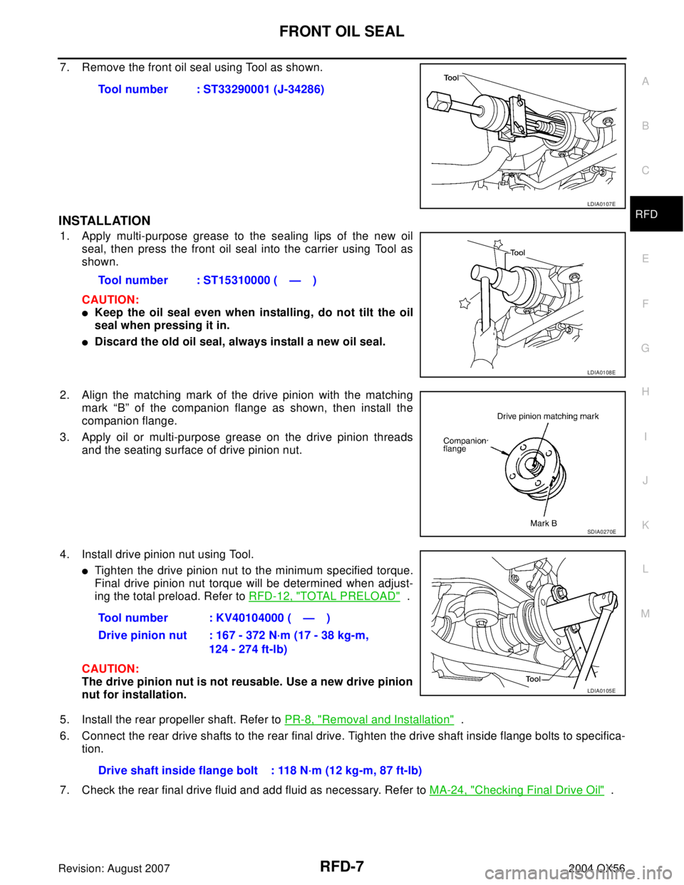
7. Remove the front oil seal using Tool as shown.
INSTALLATION
1. Apply multi-purpose grease to the sealing lips of the new oil
seal, then press the front oil seal into the carrier using Tool as
shown.
CAUTION:
�Keep the oil seal even when installing, do not tilt the oil
seal when pressing it in.
�Discard the old oil seal, always install a new oil seal.
2. Align the matching mark of the drive pinion with the matching
mark “B” of the companion flange as shown, then install the
companion flange.
3. Apply oil or multi-purpose grease on the drive pinion threads
and the seating surface of drive pinion nut.
4. Install drive pinion nut using Tool.
�Tighten the drive pinion nut to the minimum specified torque.
Final drive pinion nut torque will be determined when adjust-
ing the total preload. Refer to RFD-12, "
TOTAL PRELOAD" .
CAUTION:
The drive pinion nut is not reusable. Use a new drive pinion
nut for installation.
5. Install the rear propeller shaft. Refer to PR-8, "
Removal and Installation" .
6. Connect the rear drive shafts to the rear final drive. Tighten the drive shaft inside flange bolts to specifica-
tion.
7. Check the rear final drive fluid and add fluid as necessary. Refer to MA-24, "
Checking Final Drive Oil" . Tool number : ST33290001 (J-34286)
LDIA0107E
Tool number : ST15310000 ( — )
LDIA0108E
SDIA0270E
Tool number : KV40104000 ( — )
Drive pinion nut : 167 - 372 N·m (17 - 38 kg-m,
124 - 274 ft-lb)
LDIA0105E
Drive shaft inside flange bolt : 118 N·m (12 kg-m, 87 ft-lb)
Page 2839 of 3371
RFD-8
SIDE OIL SEAL
Revision: August 20072004 QX56
SIDE OIL SEALPFP:33142
Removal and InstallationEDS002JL
REMOVAL
1. Remove the drive shaft inside flange bolts to disconnect the rear drive shafts from the rear final drive.
Support the rear drive shaft using a suitable wire.
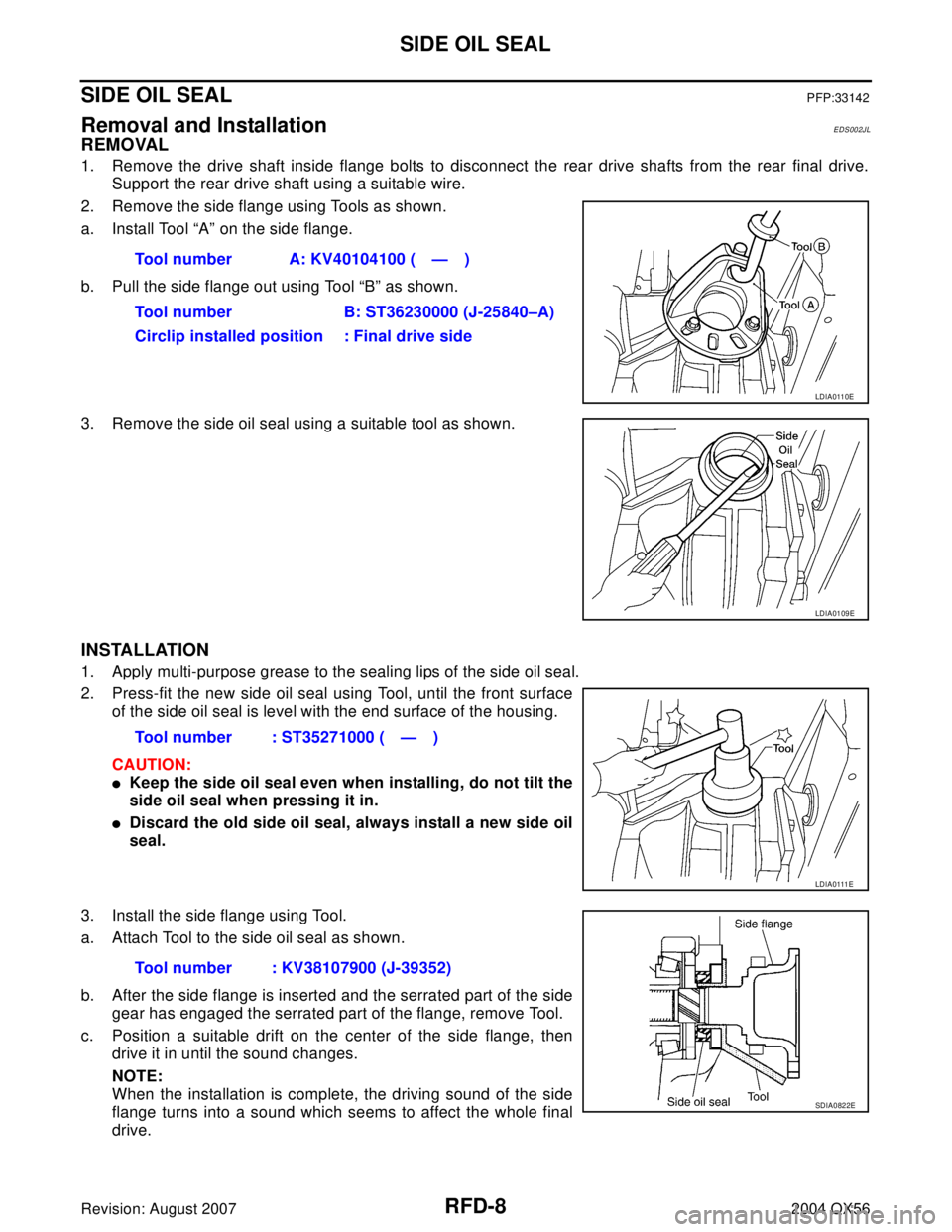
2. Remove the side flange using Tools as shown.
a. Install Tool “A” on the side flange.
b. Pull the side flange out using Tool “B” as shown.
3. Remove the side oil seal using a suitable tool as shown.
INSTALLATION
1. Apply multi-purpose grease to the sealing lips of the side oil seal.
2. Press-fit the new side oil seal using Tool, until the front surface
of the side oil seal is level with the end surface of the housing.
CAUTION:
�Keep the side oil seal even when installing, do not tilt the
side oil seal when pressing it in.
�Discard the old side oil seal, always install a new side oil
seal.
3. Install the side flange using Tool.
a. Attach Tool to the side oil seal as shown.
b. After the side flange is inserted and the serrated part of the side
gear has engaged the serrated part of the flange, remove Tool.
c. Position a suitable drift on the center of the side flange, then
drive it in until the sound changes.
NOTE:
When the installation is complete, the driving sound of the side
flange turns into a sound which seems to affect the whole final
drive.Tool number A: KV40104100 ( — )
Tool number B: ST36230000 (J-25840–A)
Circlip installed position : Final drive side
LDIA0110E
LDIA0109E
Tool number : ST35271000 ( — )
LDIA0111E
Tool number : KV38107900 (J-39352)
SDIA0822E
Page 2843 of 3371
RFD-12
REAR FINAL DRIVE ASSEMBLY
Revision: August 20072004 QX56
CAUTION:
Final drive pinion nut torque will be determined when adjusting the total preload. Refer to RFD-12,
"TOTAL PRELOAD" .
Pre-InspectionEDS002JO
Before disassembling the rear final drive, perform the following inspections.
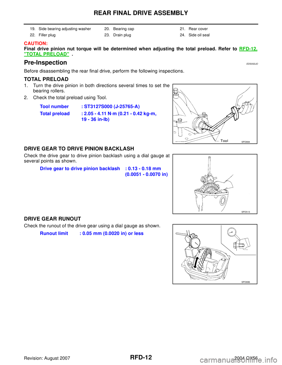
TOTAL PRELOAD
1. Turn the drive pinion in both directions several times to set the
bearing rollers.
2. Check the total preload using Tool.
DRIVE GEAR TO DRIVE PINION BACKLASH
Check the drive gear to drive pinion backlash using a dial gauge at
several points as shown.
DRIVE GEAR RUNOUT
Check the runout of the drive gear using a dial gauge as shown.
19. Side bearing adjusting washer 20. Bearing cap 21. Rear cover
22. Filler plug 23. Drain plug 24. Side oil seal
Tool number : ST3127S000 (J-25765-A)
Total preload : 2.05 - 4.11 N·m (0.21 - 0.42 kg-m,
19 - 36 in-lb)
SPD8 84
Drive gear to drive pinion backlash : 0.13 - 0.18 mm
(0.0051 - 0.0070 in)
SPD5 13
Runout limit : 0.05 mm (0.0020 in) or less
SPD8 86