Page 2846 of 3371
REAR FINAL DRIVE ASSEMBLY
RFD-15
C
E
F
G
H
I
J
K
L
MA
B
RFD
Revision: August 20072004 QX56
3. Remove the drive pinion together with the rear bearing inner
race and the bearing adjusting spacer.
4. Remove the front oil seal. Refer to RFD-6, "
FRONT OIL SEAL"
.
5. Remove the pinion front bearing inner race.
6. Remove the side oil seal. Refer to RFD-8, "
SIDE OIL SEAL" .
7. Remove the pinion bearing outer races using a suitable brass
drift.
8. Remove the pinion rear bearing inner race and the drive pinion
height adjusting washer using Tool.
SPD8 92
SDIA0817E
Tool number: : ST30021000 ( — )
S-PD1 79
Page 2853 of 3371

RFD-22
REAR FINAL DRIVE ASSEMBLY
Revision: August 20072004 QX56
3. Install the selected pinion height adjusting washer in the drive
pinion. Using a suitable press and Tool, press-fit pinion rear
bearing inner race into the drive pinion.
4. Apply multi-purpose grease to the pinion rear bearing inner race
and pinion front bearing inner race.
5. Set the drive pinion assembly in the differential carrier as shown,
and install drive pinion using a suitable press and suitable tool.
Stop when drive pinion touches the bearing.
6. Install the front oil seal using Tool. Refer to RFD-6, "
Removal and Installation" .
7. Install the companion flange, and tighten the pinion nut to a min-
imum using Tool. Check that the threaded portion of the drive
pinion and drive pinion nut are free of oil or grease.
CAUTION:
The drive pinion nut is not reusable. Use a new drive pinion
nut for installation. Tool number : ST30022000 ( — )
SPD3 77
SDIA0826E
SPD8 96
Tool number : KV40104000 ( — )
SDIA11 45 E
Page 2854 of 3371

REAR FINAL DRIVE ASSEMBLY
RFD-23
C
E
F
G
H
I
J
K
L
MA
B
RFD
Revision: August 20072004 QX56
8. Tighten the drive pinion nut by very small increments until the
specified preload is achieved, when checking the preload, turn
drive pinion in both directions several times.
�If the pinion bearing preload is less than specification, tighten
the drive pinion nut.
�If pinion bearing preload is greater than specification, replace
the pinion bearing adjusting spacer.
INSTALLATION OF DIFFERENTIAL CASE ASSEMBLY
1. Select the side bearing adjusting washer. Refer to RFD-18, "SIDE BEARING PRELOAD" .
2. Install the differential case assembly with side bearing outer
races into the gear carrier.
3. Insert the left and right side bearing adjusting washers into place
between the side bearings and the gear carrier.
4. Install the side bearing caps. Align the matching mark on the
bearing cap with the matching mark on the gear carrier, and
tighten the bearing cap bolts to specification.
5. Install the side oil seals. Refer to RFD-8, "
Removal and Installa-
tion" . Tool number : ST3127S000 (J-25765-A)
Pinion bearing
preload: 1.77 - 2.64 N·m (0.18 - 0.26 kg-m,
16 - 23 in-lb)
SPD8 84
SPD9 19
SPD9 24
Bearing cap bolts : 93 N·m (9.5 kg-m, 69 ft-lb)
SPD8 89
Page 3129 of 3371

TF-4
PREPARATION
Revision: August 20072004 QX56
PREPARATIONPFP:00002
Special Service ToolsEDS0017H
The actual shapes of Kent-Moore tools may differ from those of special service tools illustrated here.
Tool number
(Kent-Moore No.)
Tool nameDescription
ST30021000
(—)
PullerRemoving carrier bearing
a: 110 mm (4.33 in) dia.
b: 68 mm (2.68 in) dia.
ST30031000
(—)
PullerRemoving front drive shaft bearing
a: 90 mm (3.54 in) dia.
b: 50 mm (1.97 in) dia.
ST30720000
(J-25405)
DriftInstalling mainshaft front bearing and oil seal
a: 77 mm (3.03 in) dia.
b: 55.5 mm (2.185 in) dia.
ST33220000
(—)
DriftInstallation needle bearings
a: 37 mm (1.46 in) dia.
b: 31 mm (1.22 in) dia.
c: 22 mm (0.87 in) dia.
KV40100621
(J-25273)
DriftInstalling front drive shaft front and rear bear-
ing
a: 76 mm (2.99 in) dia.
b: 69 mm (2.72 in) dia.
ST30032000
(J-26010-01)
BaseInstalling front drive shaft bearing
a: 38 mm (1.50 in) dia.
b: 80 mm (3.15 in) dia.
ST33052000
(—)
AdapterRemoving front drive shaft bearing
a: 28 mm (1.10 in) dia.
b: 22 mm (0.87 in) dia.
NT411
NT411
NT658
ZZA1046D
NT086
NT660
NT431
Page 3130 of 3371

Support ringRemoving mainshaft front bearing
Installing planetary carrier assembly
Installing oil seal
a:")
PREPARATION
TF-5
C
E
F
G
H
I
J
K
L
MA
B
TF
Revision: August 20072004 QX56
ST33200000
(J-26082)
Support ringRemoving mainshaft front bearing
Installing planetary carrier assembly
Installing oil seal
a: 74.5 mm (2.933 in) dia.
b: 62.5 mm (2.461 in) dia.
ST3532500
(—)
RemoverRemoving metal bushing
a: 215 mm (8.46 in)
b: 25 mm (0.98 in) dia.
c: M 12 x P=1.5
KV38100500
(—)
DriftInstalling front oil seal
a: 80 mm (3.15 in) dia.
b: 60 mm (2.36 in) dia.
ST30911000
(—)
PullerRemoving and installing press flange snap
ring
Installing carrier bearing
Installing mainshaft center case
a: 98 mm (3.86 in) dia.
b: 40.5 mm (1.594 in) dia.
ST33290001
(J-34286)
Outer race pullerRemoving metal bushing and oil seal
ST22452000
(J-34335)
DriftRemoving and installing press flange snap
ring
a: 45 mm (1.77 in) dia.
b: 36 mm (1.42 in) dia.
c: 400 mm (15.76 in) dia.
KV38100300
(J-25523)
DriftRemoving mainshaft rear bearing
a: 54 mm(2.13 in) dia.
b: 46 mm (1.81 in) dia.
c: 32 mm (1.26 in) dia. Tool number
(Kent-Moore No.)
Tool nameDescription
NT661
NT663
NT115
NT664
NT665
NT117
ZZA1046D
Page 3131 of 3371
TF-6
PREPARATION
Revision: August 20072004 QX56
ST35300000
(—)
DriftRemoving sun gear assembly
Removing carrier bearing
Installing metal bushing
a: 59 mm (2.32 in) dia.
b: 45 mm (1.77 in) dia.
ST33710000
(—)
DriftRemoving needle bearing
Removing metal bushing
a: 89 mm (3.5 in)
b: 30 mm (1.18 in) dia.
c: 24 mm (0.9 in) dia.
ST22360002
(J-25679-01)
DriftInstalling oil seal
a: 23 mm (0.91 in) dia.
b: 32 mm (1.26 in) dia.
ST15310000
(J-25640-B)
DriftInstalling mainshaft rear bearing
a: 96 mm (3.78 in) dia.
b: 84 mm (3.31 in) dia.
KV40105310
(—)
Support ringInstalling dust cover
Installing carrier bearing
a: 89.1 mm (3.508 in) dia.
b: 80.7 mm (3.177 in) dia.
KV31103300
(—)
DriftRemoving and installing press flange snap
ring
a: 76.3 mm (3.004 in) dia.
b: 130 mm (5.12 in) Tool number
(Kent-Moore No.)
Tool nameDescription
NT073
ZZA1057D
ZZA1091D
ZZA0908D
NT661
NT668
Page 3224 of 3371
FRONT OIL SEAL
TF-99
C
E
F
G
H
I
J
K
L
MA
B
TF
Revision: August 20072004 QX56
FRONT OIL SEALPFP:38189
Removal and InstallationEDS00315
REMOVAL
1. Partially drain the transfer fluid. Refer to MA-24, "Changing Transfer Fluid" .
2. Remove the front propeller shaft. Refer to PR-4, "
Removal and Installation" .
3. Remove the companion flange self-lock nut, using Tool.
4. Put a matching mark on top of the front drive shaft in line with
the mark on the companion flange.
CAUTION:
Use paint to make the matching mark on the front drive
shaft. Do not damage the front drive shaft.
5. Remove the companion flange, using suitable tool.
6. Remove the oil seal from the front case, using Tool.
CAUTION:
Do not damage front case.Tool number : KV40104000 ( — )
SDIA2657E
SDIA2658E
WDIA0193E
Tool number : ST33290001 (J-34286)
LDIA0144E
Page 3225 of 3371
TF-100
FRONT OIL SEAL
Revision: August 20072004 QX56
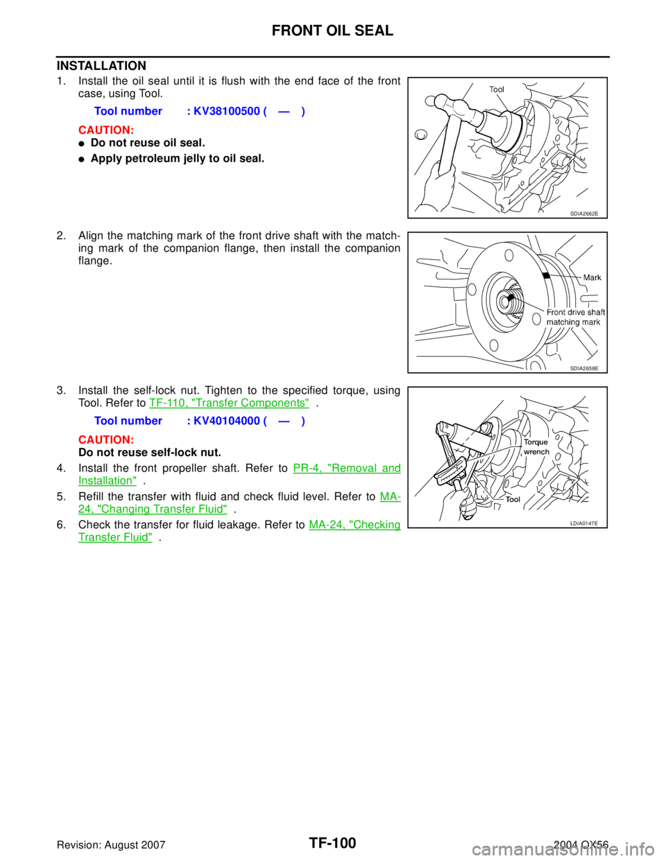
INSTALLATION
1. Install the oil seal until it is flush with the end face of the front
case, using Tool.
CAUTION:
�Do not reuse oil seal.
�Apply petroleum jelly to oil seal.
2. Align the matching mark of the front drive shaft with the match-
ing mark of the companion flange, then install the companion
flange.
3. Install the self-lock nut. Tighten to the specified torque, using
Tool. Refer to TF-110, "
Transfer Components" .
CAUTION:
Do not reuse self-lock nut.
4. Install the front propeller shaft. Refer to PR-4, "
Removal and
Installation" .
5. Refill the transfer with fluid and check fluid level. Refer to MA-
24, "Changing Transfer Fluid" .
6. Check the transfer for fluid leakage. Refer to MA-24, "
Checking
Transfer Fluid" . Tool number : KV38100500 ( — )
SDIA2662E
SDIA2658E
Tool number : KV40104000 ( — )
LDIA0147E


DriftRemoving sun gear assembly
Removing carrier bearing
Installing metal bushing
a: 59 mm (2.32 in) dia.
b: 45 mm (1.77 in) dia.
ST337")