Page 2019 of 3371
FFD-8
FRONT OIL SEAL
Revision: August 20072004 QX56
FRONT OIL SEALPFP:38189
Removal and InstallationEDS0035J
REMOVAL
1. Remove front propeller shaft. Refer to PR-5, "REMOVAL" .
2. Separate the RH and LH drive shafts from the front final drive. Refer to FA X -7 , "
REMOVAL" .
3. Measure the drive pinion bearing preload with front oil seal resistance using Tool.
NOTE:
Record the preload measurement.
4. Loosen drive pinion nut while holding the companion flange
using Tool.
5. Remove companion flange using a suitable puller.
6. Place a small hole in seal case, using a suitable punch or drill.
7. Install slide hammer tool as shown and remove seal.Tool number : ST3127S000 (J-25765-A)
Tool number : KV38108300 (J-44195)
BDIA0001E
LDIA0129E
LDIA0130E
Page 2020 of 3371
FRONT OIL SEAL
FFD-9
C
E
F
G
H
I
J
K
L
MA
B
FFD
Revision: August 20072004 QX56
INSTALLATION
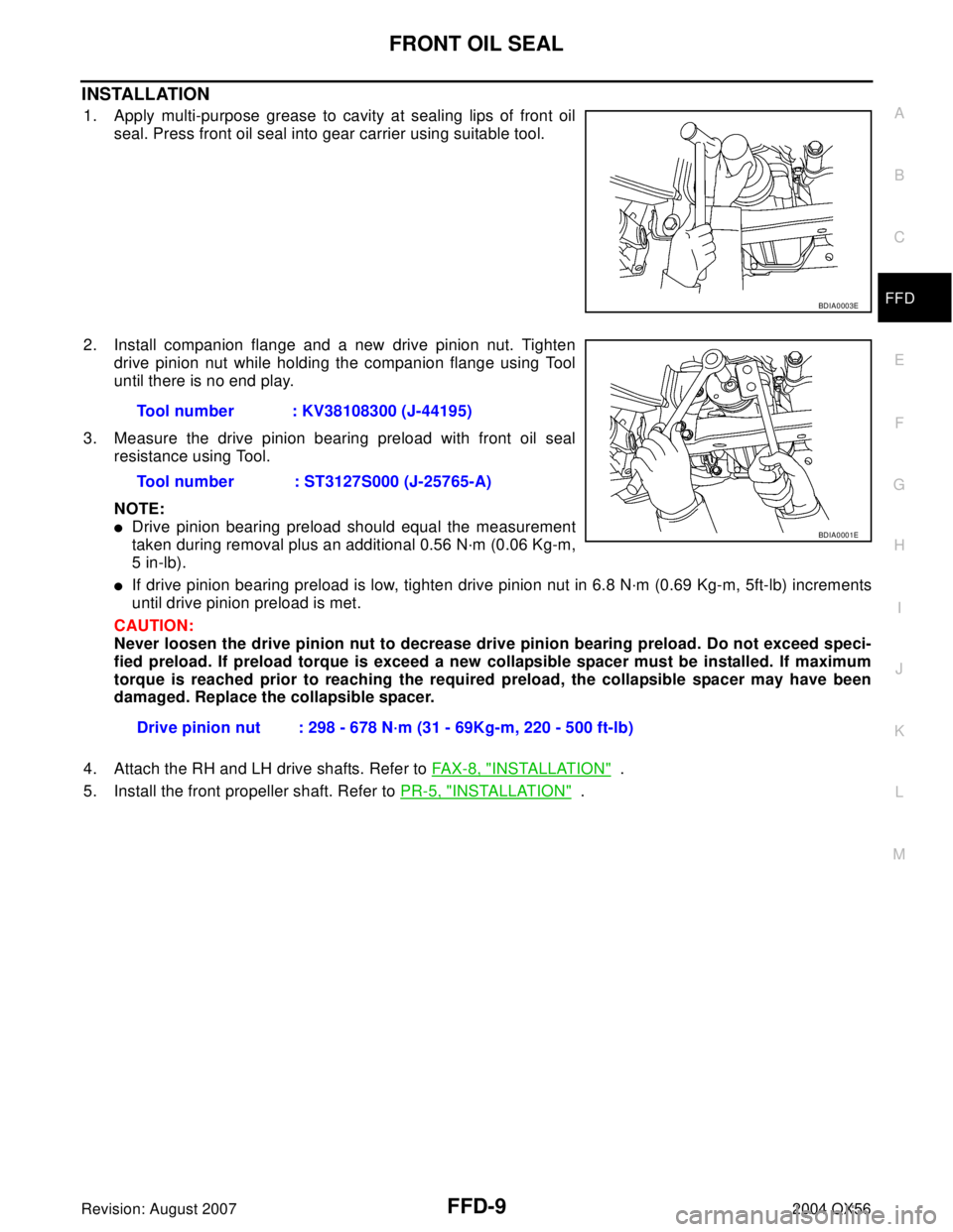
1. Apply multi-purpose grease to cavity at sealing lips of front oil
seal. Press front oil seal into gear carrier using suitable tool.
2. Install companion flange and a new drive pinion nut. Tighten
drive pinion nut while holding the companion flange using Tool
until there is no end play.
3. Measure the drive pinion bearing preload with front oil seal
resistance using Tool.
NOTE:
�Drive pinion bearing preload should equal the measurement
taken during removal plus an additional 0.56 N·m (0.06 Kg-m,
5 in-lb).
�If drive pinion bearing preload is low, tighten drive pinion nut in 6.8 N·m (0.69 Kg-m, 5ft-lb) increments
until drive pinion preload is met.
CAUTION:
Never loosen the drive pinion nut to decrease drive pinion bearing preload. Do not exceed speci-
fied preload. If preload torque is exceed a new collapsible spacer must be installed. If maximum
torque is reached prior to reaching the required preload, the collapsible spacer may have been
damaged. Replace the collapsible spacer.
4. Attach the RH and LH drive shafts. Refer to FAX-8, "
INSTALLATION" .
5. Install the front propeller shaft. Refer to PR-5, "
INSTALLATION" .
BDIA0003E
Tool number : KV38108300 (J-44195)
Tool number : ST3127S000 (J-25765-A)
Drive pinion nut : 298 - 678 N·m (31 - 69Kg-m, 220 - 500 ft-lb)
BDIA0001E
Page 2022 of 3371
REAR COVER GASKET
FFD-11
C
E
F
G
H
I
J
K
L
MA
B
FFD
Revision: August 20072004 QX56
REAR COVER GASKETPFP:38320
Removal and InstallationEDS0035L
REMOVAL
1. Remove front final drive. Refer to FFD-12, "REMOVAL" .
2. Drain gear oil. Refer to MA-25, "
Changing Final Drive Oil" .
3. Remove rear cover using Tool.
INSTALLATION
1. Apply 3.2mm (0.126 in) bead of sealant to the rear cover using
Tool.
�Use Genuine Silicone RTV sealant or equivalent. Refer to. GI-
45, "Recommended Chemical Products and Sealants" .
2. Install rear cover and tighten rear cover bolts in the order shown
FFD-11, "
INSTALLATION" .
3. Fill final drive with recommended gear oil. Refer to GI-45, "
Rec-
ommended Chemical Products and Sealants" .
4. Install front final drive. Refer to FFD-13, "
INSTALLATION" . Tool number : KV10111100 (J-37228)
Tool number :WS39930000 ( — )
SDIA3204E
WDIA0290E
Page 2026 of 3371
FRONT FINAL DRIVE ASSEMBLY
FFD-15
C
E
F
G
H
I
J
K
L
MA
B
FFD
Revision: August 20072004 QX56
ASSEMBLY INSPECTION AND ADJUSTMENT
�Before inspection and adjustment, drain gear oil.
Total Preload Torque
1. Rotate drive pinion back and forth 2 to 3 times to check for unusual noise and rotation malfunction.
2. Rotate drive pinion at least 20 times to check for smooth operation of the bearing.
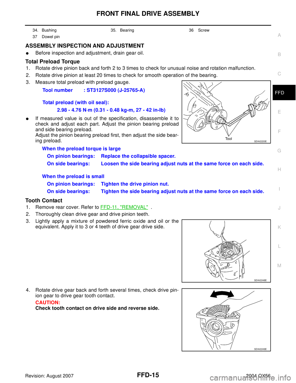
3. Measure total preload with preload gauge.
�If measured value is out of the specification, disassemble it to
check and adjust each part. Adjust the pinion bearing preload
and side bearing preload.
Adjust the pinion bearing preload first, then adjust the side bear-
ing preload.
Tooth Contact
1. Remove rear cover. Refer to FFD-11, "REMOVAL" .
2. Thoroughly clean drive gear and drive pinion teeth.
3. Lightly apply a mixture of powdered ferric oxide and oil or the
equivalent. Apply it to 3 or 4 teeth of drive gear drive side.
4. Rotate drive gear back and forth several times, check drive pin-
ion gear to drive gear tooth contact.
CAUTION:
Check tooth contact on drive side and reverse side.
34. Bushing 35. Bearing 36 Screw
37 Dowel pin
Tool number : ST3127S000 (J-25765-A)
Total preload (with oil seal):
2.98 - 4.76 N·m (0.31 - 0.48 kg-m, 27 - 42 in-lb)
SDIA2220E
When the preload torque is large
On pinion bearings: Replace the collapsible spacer.
On side bearings: Loosen the side bearing adjust nuts at the same force on each side.
When the preload is small
On pinion bearings: Tighten the drive pinion nut.
On side bearings: Tighten the side bearing adjust nuts at the same force on each side.
SDIA2248E
SDIA2249E
Page 2033 of 3371
FFD-22
FRONT FINAL DRIVE ASSEMBLY
Revision: August 20072004 QX56
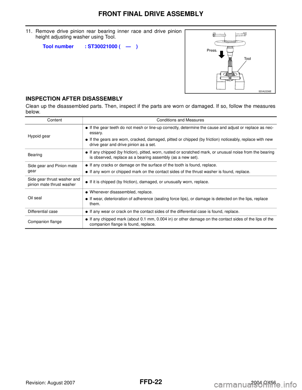
11. Remove drive pinion rear bearing inner race and drive pinion
height adjusting washer using Tool.
INSPECTION AFTER DISASSEMBLY
Clean up the disassembled parts. Then, inspect if the parts are worn or damaged. If so, follow the measures
below.Tool number : ST30021000 ( — )
SDIA2236E
Content Conditions and Measures
Hypoid gear
�If the gear teeth do not mesh or line-up correctly, determine the cause and adjust or replace as nec-
essary.
�If the gears are worn, cracked, damaged, pitted or chipped (by friction) noticeably, replace with new
drive gear and drive pinion as a set.
Bearing
�If any chipped (by friction), pitted, worn, rusted or scratched mark, or unusual noise from the bearing
is observed, replace as a bearing assembly (as a new set).
Side gear and Pinion mate
gear
�If any cracks or damage on the surface of the tooth is found, replace.
�If any worn or chipped mark on the contact sides of the thrust washer is found, replace.
Side gear thrust washer and
pinion mate thrust washer
�If it is chipped (by friction), damaged, or unusually worn, replace.
Oil seal
�Whenever disassembled, replace.
�If wear, deterioration of adherence (sealing force lips), or damage is detected on the lips, replace
them.
Differential case
�If any wear or crack on the contact sides of the differential case is found, replace.
Companion flange
�If any chipped mark (about 0.1 mm, 0.004 in) or other damage on the contact sides of the lips of the
companion flange is found, replace.
Page 2036 of 3371
FRONT FINAL DRIVE ASSEMBLY
FFD-25
C
E
F
G
H
I
J
K
L
MA
B
FFD
Revision: August 20072004 QX56
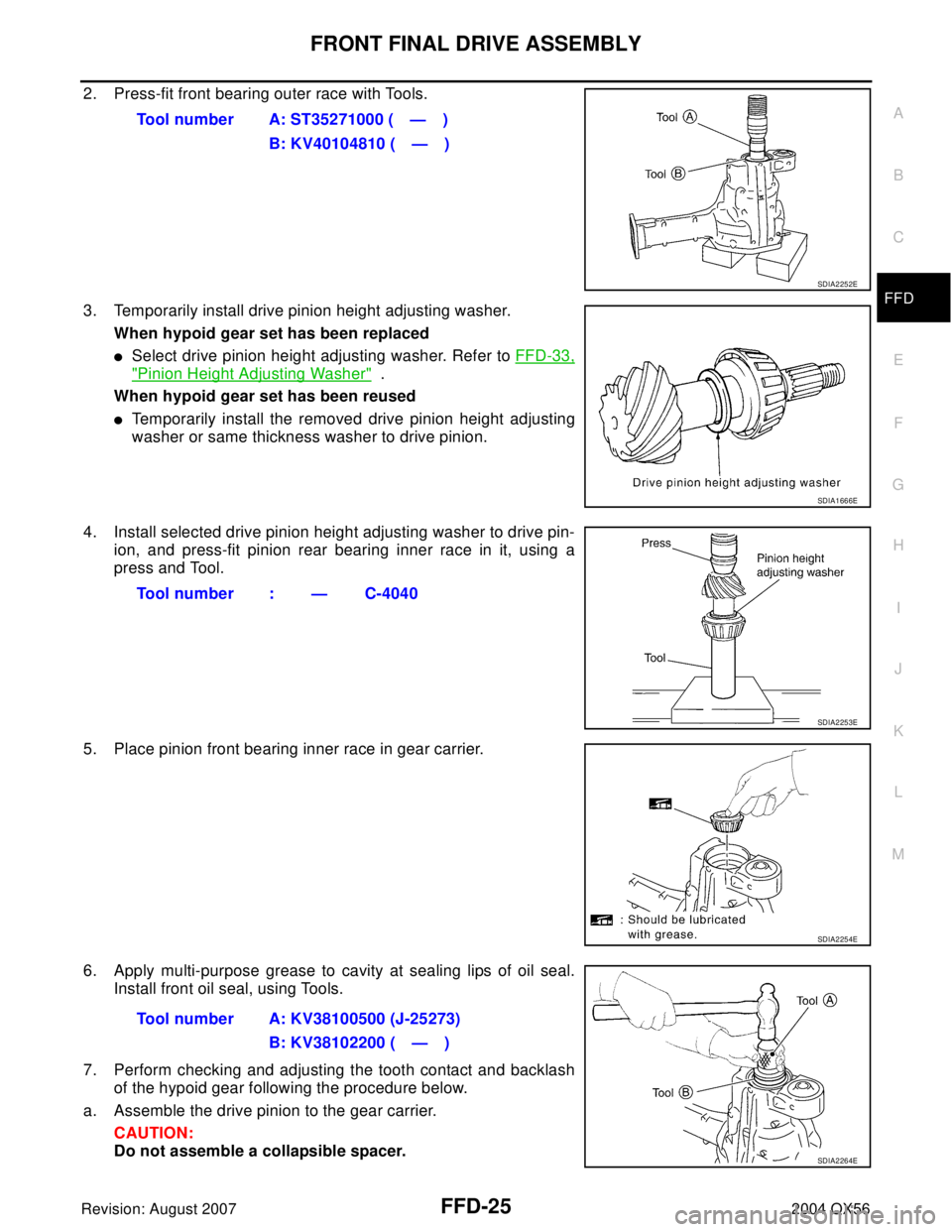
2. Press-fit front bearing outer race with Tools.
3. Temporarily install drive pinion height adjusting washer.
When hypoid gear set has been replaced
�Select drive pinion height adjusting washer. Refer to FFD-33,
"Pinion Height Adjusting Washer" .
When hypoid gear set has been reused
�Temporarily install the removed drive pinion height adjusting
washer or same thickness washer to drive pinion.
4. Install selected drive pinion height adjusting washer to drive pin-
ion, and press-fit pinion rear bearing inner race in it, using a
press and Tool.
5. Place pinion front bearing inner race in gear carrier.
6. Apply multi-purpose grease to cavity at sealing lips of oil seal.
Install front oil seal, using Tools.
7. Perform checking and adjusting the tooth contact and backlash
of the hypoid gear following the procedure below.
a. Assemble the drive pinion to the gear carrier.
CAUTION:
Do not assemble a collapsible spacer.Tool number A: ST35271000 ( — )
B: KV40104810 ( — )
SDIA2252E
SDIA1666E
Tool number : — C-4040
SDIA2253E
SDIA2254E
Tool number A: KV38100500 (J-25273)
B: KV38102200 ( — )
SDIA2264E
Page 2038 of 3371
FRONT FINAL DRIVE ASSEMBLY
FFD-27
C
E
F
G
H
I
J
K
L
MA
B
FFD
Revision: August 20072004 QX56
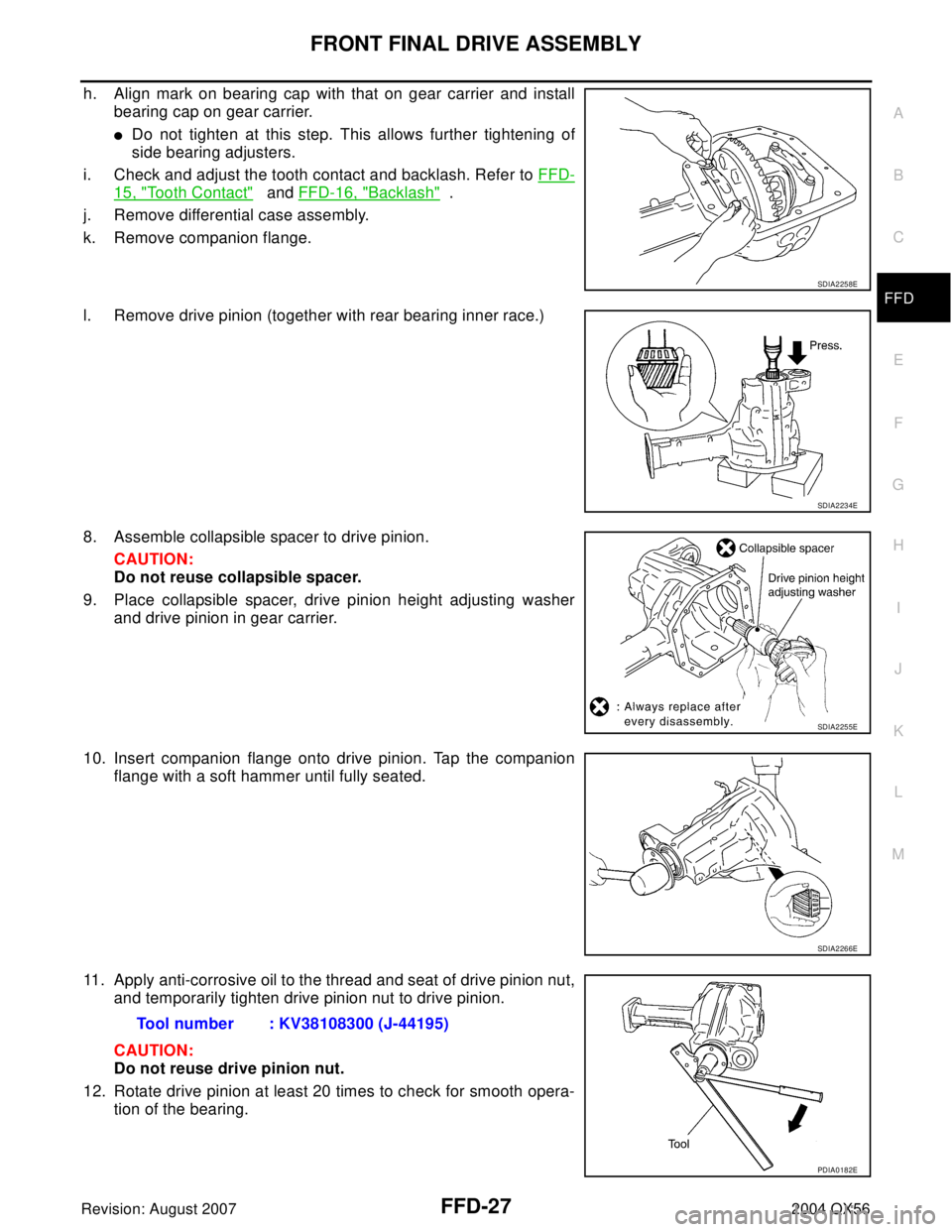
h. Align mark on bearing cap with that on gear carrier and install
bearing cap on gear carrier.
�Do not tighten at this step. This allows further tightening of
side bearing adjusters.
i. Check and adjust the tooth contact and backlash. Refer to FFD-
15, "Tooth Contact" and FFD-16, "Backlash" .
j. Remove differential case assembly.
k. Remove companion flange.
l. Remove drive pinion (together with rear bearing inner race.)
8. Assemble collapsible spacer to drive pinion.
CAUTION:
Do not reuse collapsible spacer.
9. Place collapsible spacer, drive pinion height adjusting washer
and drive pinion in gear carrier.
10. Insert companion flange onto drive pinion. Tap the companion
flange with a soft hammer until fully seated.
11. Apply anti-corrosive oil to the thread and seat of drive pinion nut,
and temporarily tighten drive pinion nut to drive pinion.
CAUTION:
Do not reuse drive pinion nut.
12. Rotate drive pinion at least 20 times to check for smooth opera-
tion of the bearing.
SDIA2258E
SDIA2234E
SDIA2255E
SDIA2266E
Tool number : KV38108300 (J-44195)
PDIA0182E
Page 2039 of 3371
FFD-28
FRONT FINAL DRIVE ASSEMBLY
Revision: August 20072004 QX56
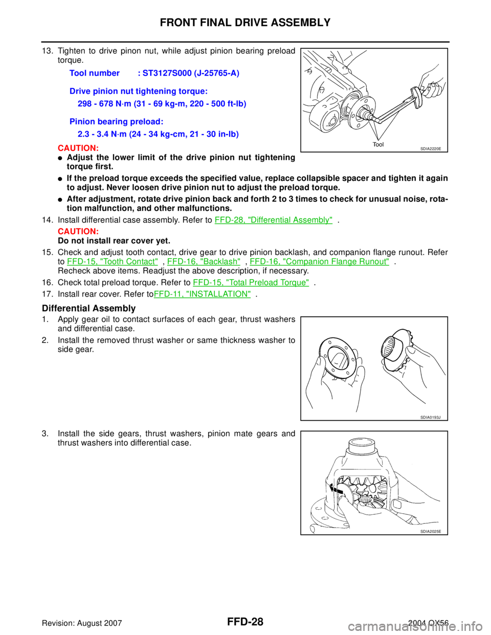
13. Tighten to drive pinon nut, while adjust pinion bearing preload
torque.
CAUTION:
�Adjust the lower limit of the drive pinion nut tightening
torque first.
�If the preload torque exceeds the specified value, replace collapsible spacer and tighten it again
to adjust. Never loosen drive pinion nut to adjust the preload torque.
�After adjustment, rotate drive pinion back and forth 2 to 3 times to check for unusual noise, rota-
tion malfunction, and other malfunctions.
14. Install differential case assembly. Refer to FFD-28, "
Differential Assembly" .
CAUTION:
Do not install rear cover yet.
15. Check and adjust tooth contact, drive gear to drive pinion backlash, and companion flange runout. Refer
to FFD-15, "
Tooth Contact" , FFD-16, "Backlash" , FFD-16, "Companion Flange Runout" .
Recheck above items. Readjust the above description, if necessary.
16. Check total preload torque. Refer to FFD-15, "
Total Preload Torque" .
17. Install rear cover. Refer toFFD-11, "
INSTALLATION" .
Differential Assembly
1. Apply gear oil to contact surfaces of each gear, thrust washers
and differential case.
2. Install the removed thrust washer or same thickness washer to
side gear.
3. Install the side gears, thrust washers, pinion mate gears and
thrust washers into differential case.Tool number : ST3127S000 (J-25765-A)
Drive pinion nut tightening torque:
298 - 678 N·m (31 - 69 kg-m, 220 - 500 ft-lb)
Pinion bearing preload:
2.3 - 3.4 N·m (24 - 34 kg-cm, 21 - 30 in-lb)
SDIA2220E
SDIA0193J
SDIA2025E