Page 1963 of 3371

EM-80Revision: August 2007
CYLINDER BLOCK
2004 QX56
�Assemble so that the front mark on the piston crown and the
oil holes and the cylinder No. on the connecting rod are posi-
tioned as shown.
c. Install the snap ring to the grooves of the piston front side.
�Insert it fully into groove to install.
�After installing, make sure the connecting rod moves
smoothly.
11. Install the piston rings.
CAUTION:
Be careful not to damage the piston.
�Position each ring with the gap as shown, referring to the pis-
ton front mark.
�Install the second ring with the stamped surface facing
upward.
12. Install the connecting rod bearings to the connecting rod and the
connecting rod cap.
�When installing the connecting rod bearings, apply engine oil
to the bearing surface (inside). Do not apply oil to the back
surface, but thoroughly clean it.
�When installing, align the connecting rod bearing stopper pro-
trusion with the cutout of the connecting rod to install.
�Check the oil holes on the connecting rod and those on the
corresponding bearing are aligned.
13. Install the piston and connecting rod assembly to the crankshaft
using Tool.
�Position the crankshaft pin corresponding to the connecting
rod to be installed onto the bottom dead center.
�Apply engine oil sufficiently to the cylinder bore, piston, and
crankshaft pin.
�Match the cylinder position with the cylinder No. on the con-
necting rod to install.
�Install the piston with the front mark on the piston crown fac-
ing the front of the engine.
CAUTION:
Be careful not to damage the crankshaft pin, resulting from an interference of the connecting
rod big end.
KBIA2534E
Stamped mark Second ring : 2N
PBIC0100E
PBIC0266E
Tool number : EM03470000 (J-8037)
KBIA2535E
Page 1964 of 3371

CYLINDER BLOCK
EM-81
C
D
E
F
G
H
I
J
K
L
MA
EM
Revision: August 20072004 QX56
14. Install the connecting rod cap.
�Match the stamped cylinder number marks on the connecting
rod with those on the cylinder cap to install.
15. Tighten the connecting rod bolts using Tool.
�Apply engine oil to the threads and seats of the connecting
rod bolts.
�After tightening the bolts, make sure that the crankshaft
rotates smoothly.
�Check the connecting rod side clearance. Refer to EM-89, "CONNECTING ROD SIDE CLEARANCE"
16. Install knock sensor.
CAUTION:
If the knock sensor is dropped, replace it with a new one.
�Make sure that there is no foreign material on the cylinder
block mating surface and the back surface of the knock sen-
sor.
�Install it with its connector facing the center of cylinder block
side.
�Do not tighten the knock sensor bolts while holding the con-
nector.
�Make sure that the knock sensor does not interfere with other
parts.
�Position sub-harness as shown before installing intake mani-
fold.
17. Installation of the remaining components is in the reverse order of removal.
18. Remove engine assembly from engine stand.
KBIA2536E
Tool number : KV10112100 (BT-8653-A)
Connecting rod bolts
Step 1 : 19.6 N·m (1.5 kg-m, 11 ft-lb)
Step 2 : 90° clockwise
WBIA0586E
KBIA2493E
KBIA2549E
Page 2004 of 3371

DRIVE SHAFT
FAX-7
C
E
F
G
H
I
J
K
L
MA
B
FA X
Revision: August 20072004 QX56
DRIVE SHAFTPFP:39100
Removal and InstallationEDS001B5
REMOVAL
1. Remove wheel and tire using power tool.
2. Remove engine under cover using power tool.
3. Remove wheel sensor harness from mount on knuckle.
CAUTION:
Do not pull on wheel sensor harness.
4. Without disassembling the hydraulic lines, remove brake caliper using power tool. Reposition it aside with
wire. Refer to BR-22, "
Removal and Installation of Brake Caliper and Disc Rotor" .
NOTE:
Avoid depressing brake pedal while brake caliper is removed.
5. Remove coil spring and shock absorber assembly using power tool. Refer to FSU-10, "
Removal and
Installation" .
6. Separate upper link ball joint stud from steering knuckle using
Tool.
�Support lower link with jack.
7. Remove cotter pin, then remove drive shaft nut.
8. Remove drive shaft mounting bolts from front final drive.
9. Remove drive shaft from wheel hub and bearing assembly.
CAUTION:
�When removing drive shaft, do not apply an excessive
angle to drive shaft joint. Also be careful not to exces-
sively extend slide joint.
INSPECTION AFTER REMOVAL
�Move joint up, down, left, right, and in axial direction. Check for any rough movement or significant loose-
ness.
�Check boot for cracks or other damage, and for grease leakage.
�If damaged, disassemble drive shaft to verify damage, and
repair or replace as necessary.
1. Cotter pin 2. Drive shaft nut 3. Drive shaft
LDIA0159E
Tool number : ST29020001 (J-24319-01)
LEIA0095E
RAA0030D
Page 2013 of 3371

FFD-2
PRECAUTIONS
Revision: August 20072004 QX56
PRECAUTIONSPFP:00001
PrecautionsEDS0035E
CAUTION:
�Before starting diagnosis of the vehicle, understand symptoms well. Perform correct and system-
atic operations.
�Check for the correct installation status prior removal or disassembly. When matching marks are
required, be sure they do not interfere with the function of the parts they are applied to.
�Carry out an overhaul in a clean work place, Using a dust proof room is recommended.
�Before disassembly, using steam or white gasoline, completely remove sand and mud from the
exterior the unit, preventing them from entering into the unit during disassembly or assembly.
�Check appearance of the disassembled parts for damage, deformation, and abnormal wear. If a
malfunction is detected, replace it with a new one.
�Normally replace lock pins, oil seals, and bearings with new ones every times they are removed.
�In principle, tighten bolts or nuts gradually in several steps working diagonally from inside to out-
side. If tightening sequence is specified, observe it.
�Clean and flush the parts sufficiently and blow them dry.
�Be careful not to damage the sliding surfaces and mating surface.
�When applying sealant, remove the old sealant from the mounting surface; then remove any mois-
ture, oil, and foreign materials from the application and mounting surfaces.
�Always use shop paper for cleaning the inside of components.
�Avoid using cotton gloves or a shop cloth to prevent entering of lint.
�During assembly, observe the specified tightening torque, and new differential gear oil, Vaseline,
or multi-purpose grease, as specified for each vehicle, when necessary.
Precautions for Liquid GasketEDS0035F
REMOVAL OF LIQUID GASKET SEALING
�After removing nuts and bolts, separate the mating surface and
remove old liquid gasket sealing using Tool.
CAUTION:
Be careful not to damage the mating surfaces.
�Tap seal cutter to insert it, and then slide it by tapping on the
side as shown.
�In areas where Tool is difficult to use, use plastic hammer to
lightly tap the parts, to remove it.
CAUTION:
If for some unavoidable reason tool such as screwdriver is
used, be careful not to damage the mating surfaces.
LIQUID GASKET APPLICATION PROCEDURE
1. Using scraper, remove old liquid gasket adhering to the gasket
application surface and the mating surface.
�Remove liquid gasket completely from the groove of the gas-
ket application surface, bolts, and bolt holes.
2. Thoroughly clean the mating surfaces and remove adhering
moisture, grease and foreign materials.Tool number : KV10111100 (J-37228)
WBIA0566E
PBIC0003E
Page 2014 of 3371

PRECAUTIONS
FFD-3
C
E
F
G
H
I
J
K
L
MA
B
FFD
Revision: August 20072004 QX56
3. Attach liquid gasket tube to Tool.
Use Genuine RTV Silicone Sealant or equivalent. Refer to
GI-45, "
Recommended Chemical Products and Sealants" .
4. Apply liquid gasket without breaks to the specified location with
the specified dimensions.
�If there is a groove for liquid gasket application, apply liquid
gasket to the groove.
�As for bolt holes, normally apply liquid gasket inside the
holes. Occasionally, it should be applied outside the holes.
Make sure to read the text of this manual.
�Within five minutes of liquid gasket application, install the mat-
ing component.
�If liquid gasket protrudes, wipe it off immediately.
�Do not retighten nuts or bolts after the installation.
�After 30 minutes or more have passed from the installation, fill
engine oil and engine coolant.
CAUTION:
If there are specific instructions in this manual, observe
them.Tool number : WS39930000 ( — )
WBIA0567E
SEM 15 9F
Page 2015 of 3371

FFD-4
PREPARATION
Revision: August 20072004 QX56
PREPARATIONPFP:00002
Special Service ToolsEDS0035G
The actual shapes of Kent-Moore tools may differ from those of special service tools illustrated here.
Tool number
(Kent-Moore No.)
Tool nameDescription
KV10111100
(J-37228)
Seal cutterRemoving steel oil pan and rear timing chain
case
WS39930000
(—)
Tube presserPressing the tube of liquid gasket
ST35271000
(—)
DriftInstalling drive pinion front bearing outer
race.
a: 72 mm (2.83 in) dia.
b: 36 mm (1.42 in) dia.
KV38100500
(J-25273)
DriftInstalling front oil seal.
a: 80 mm (3.15 in) dia.
b: 60 mm (2.36 in) dia.
ST30021000
(—)
Puller
�Removing side bearing inner race.
�Removing drive pinion rear bearing inner
race.
KV38100300
(J-25523)
DriftInstalling side bearing inner race.
a: 54 mm (2.13 in) dia.
b: 46 mm (1.81 in) dia.
c: 32mm (1.26 in) dia.
ST30901000
(—)
DriftInstalling drive pinion rear bearing outer race.
A: 79mm (3.11 in) dia.
B: 45 mm (1.77 in) dia.
C: 35.2 mm (1.39 in) dia.
S-NT046
S-NT052
ZZA0702D
ZZA0811D
ZZA0700D
ZZA1046D
SDIA0217J
Page 2016 of 3371

DriftInstalling drive pinion front bearing outer
race.
a: 68 mm (2.68 in) dia.
b: 55 mm (2.17 in) dia.
KV3")
PREPARATION
FFD-5
C
E
F
G
H
I
J
K
L
MA
B
FFD
Revision: August 20072004 QX56
KV40104810
(—)
DriftInstalling drive pinion front bearing outer
race.
a: 68 mm (2.68 in) dia.
b: 55 mm (2.17 in) dia.
KV38102200
(—)
DriftInstalling front oil seal.
a: 90 mm (3.54 in) dia.
b: 55.3 mm (2.18 in) dia.
c: 31 mm (1.22 in) dia,
ST33081000
(—)
AdapterRemoving and installing side bearing inner
race.
a: 33.5 mm (1.32 in) dia.
b: 43 mm (1.69 in) dia.
KV38108300
(J-44195)
Companion flange wrenchRemoving and installing drive pinion nut.
ST3127S000
(J-25765-A)
Preload gauge
1. GG91030000
(J-25765)
Torque wrench
2. HT62940000
( — )
Socket adapter (1/2″)
3. HT62900000
( — )
Socket adapter (3/8″)Inspecting drive pinion bearing preload and
total preload
—
(C-4040)
InstallerInstalling drive pinion rear bearing inner race.
KV40105230
(—)
DriftInstalling drive pinion rear bearing outer race.
a: 92 mm(3.62 in) dia.
b: 86 mm (3.39 in) dia. Tool number
(Kent-Moore No.)
Tool nameDescription
ZZA1003D
NT107
ZZA0881D
NT771
NT124
SDIA2607E
ZZA1141D
Page 2017 of 3371
FFD-6
PREPARATION
Revision: August 20072004 QX56
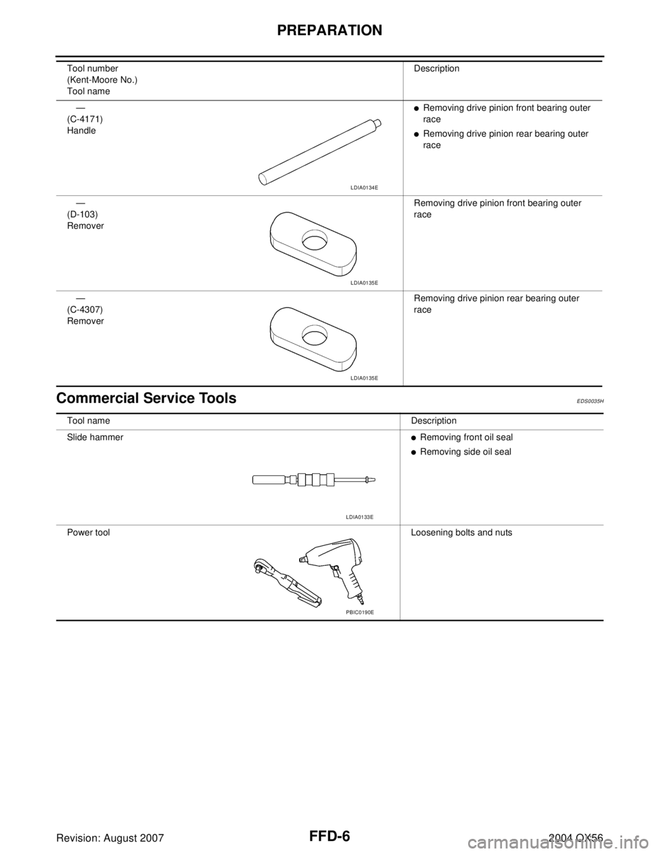
Commercial Service ToolsEDS0035H
—
(C-4171)
Handle�Removing drive pinion front bearing outer
race
�Removing drive pinion rear bearing outer
race
—
(D-103)
RemoverRemoving drive pinion front bearing outer
race
—
(C-4307)
RemoverRemoving drive pinion rear bearing outer
race Tool number
(Kent-Moore No.)
Tool nameDescription
LDIA0134E
LDIA0135E
LDIA0135E
Tool nameDescription
Slide hammer
�Removing front oil seal
�Removing side oil seal
Power toolLoosening bolts and nuts
LDIA0133E
PBIC0190E