Page 2780 of 3371
POWER STEERING OIL PUMP
PS-29
C
D
E
F
H
I
J
K
L
MA
B
PS
Revision: August 20072004 QX56
2. Install oil seal to body assembly using suitable tool.
NOTE:
Do not reuse oil seal.
3. Apply a coat of Genuine NISSAN PSF or equivalent to drive shaft assembly and press drive shaft assem-
bly into body assembly with suitable tool, then install snap ring.
NOTE:
Do not reuse snap ring.
4. Apply a coat of Genuine NISSAN PSF or equivalent to O-ring and install O-ring into body assembly.
NOTE:
Do not reuse O-ring.
5. Install side plate to body assembly.
6. Install lock pin into lock pin hole, and install cam-ring as shown.
�When installing cam ring, align letter "E" to rear cover as
shown.
CAUTION:
Do not confuse the assembling direction of cam ring. If
cam ring is installed facing the incorrect direction, it may
cause pump operation malfunction.
7. Install rotor to body assembly.
SST 0 38 A
SGIA0422E
WGIA0079E
Page 2781 of 3371
PS-30
POWER STEERING OIL PUMP
Revision: August 20072004 QX56
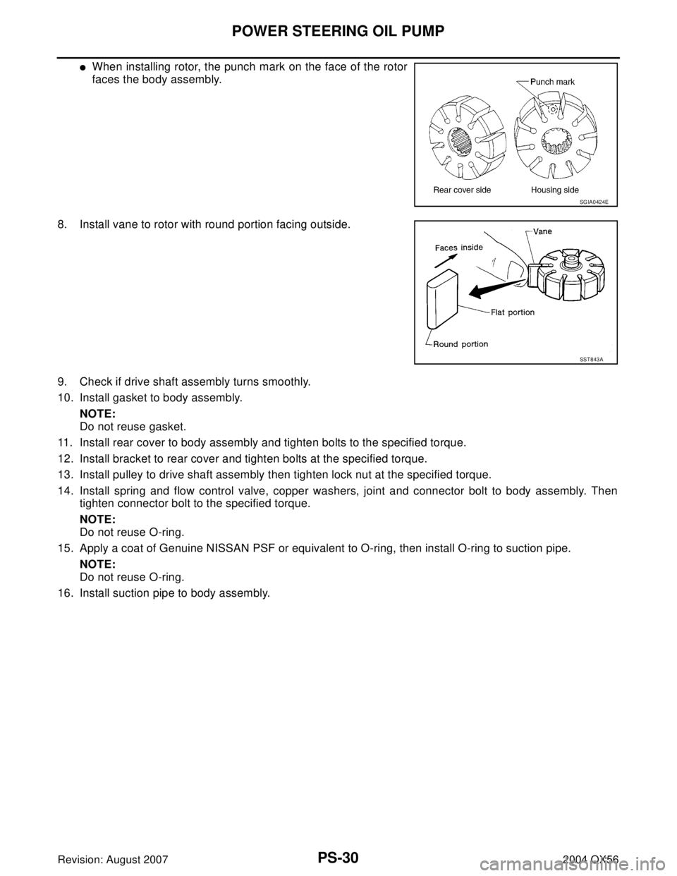
�When installing rotor, the punch mark on the face of the rotor
faces the body assembly.
8. Install vane to rotor with round portion facing outside.
9. Check if drive shaft assembly turns smoothly.
10. Install gasket to body assembly.
NOTE:
Do not reuse gasket.
11. Install rear cover to body assembly and tighten bolts to the specified torque.
12. Install bracket to rear cover and tighten bolts at the specified torque.
13. Install pulley to drive shaft assembly then tighten lock nut at the specified torque.
14. Install spring and flow control valve, copper washers, joint and connector bolt to body assembly. Then
tighten connector bolt to the specified torque.
NOTE:
Do not reuse O-ring.
15. Apply a coat of Genuine NISSAN PSF or equivalent to O-ring, then install O-ring to suction pipe.
NOTE:
Do not reuse O-ring.
16. Install suction pipe to body assembly.
SGIA0424E
SST 8 43 A
Page 2782 of 3371
HYDRAULIC LINE
PS-31
C
D
E
F
H
I
J
K
L
MA
B
PS
Revision: August 20072004 QX56
HYDRAULIC LINEPFP:49721
Removal and InstallationEGS000MZ
Refer to the following illustration for hydralic line removal.
1. Reservoir tank 2. Suction hose 3. High pressure hose
4. Oil cooler 5. Steering gear assembly 6. Reservoir tank bracket
7. Eye bolt
WGIA0096E
Page 2783 of 3371
PS-32
HYDRAULIC LINE
Revision: August 20072004 QX56
Installation is in the reverse order of removal.
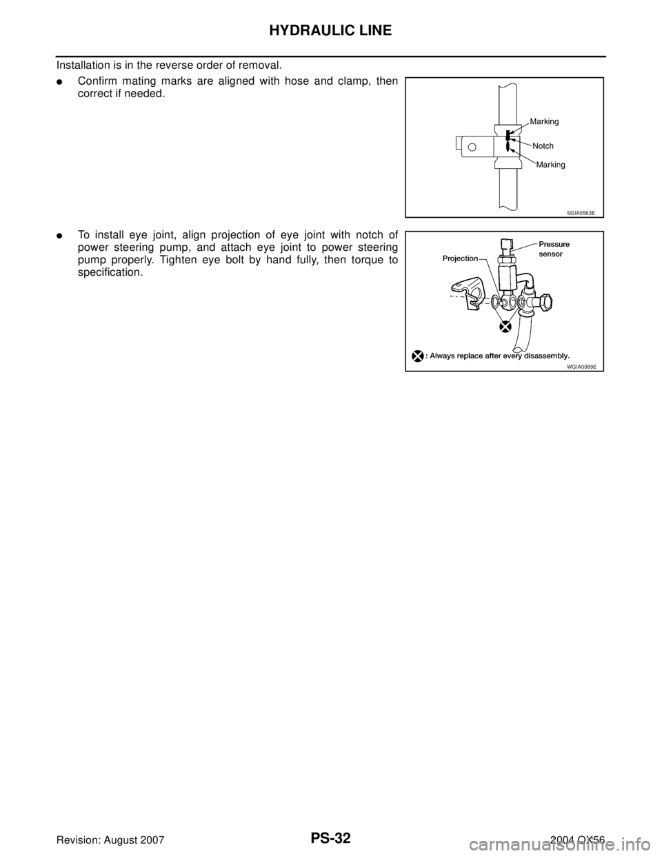
�Confirm mating marks are aligned with hose and clamp, then
correct if needed.
�To install eye joint, align projection of eye joint with notch of
power steering pump, and attach eye joint to power steering
pump properly. Tighten eye bolt by hand fully, then torque to
specification.
SGIA0563E
WGIA0089E
Page 2784 of 3371
SERVICE DATA AND SPECIFICATIONS (SDS)
PS-33
C
D
E
F
H
I
J
K
L
MA
B
PS
Revision: August 20072004 QX56
SERVICE DATA AND SPECIFICATIONS (SDS)PFP:00030
Steering WheelEGS000NE
Steering ColumnEGS000NG
Inspection After Assembly
Unit: mm (in)
Inspection After Removal
Unit: mm (in) End play of the axial direction for steering wheel 0 mm (0 in)
Steering wheel play on the outer circumference 0 − 35 mm (0 − 1.38 in)
Steering wheel turning force 39 N (4 kg-f, 9 lb-f) or less
Steering column length “L”610 (24.02)
WGIA0080E
Steering column length “L2”262 (10.31)
Steering column length “L1” 158 (6.22)
SGIA0475E
Page 2785 of 3371
PS-34
SERVICE DATA AND SPECIFICATIONS (SDS)
Revision: August 20072004 QX56
Inspection After Installation
Steering Outer Socket and Inner SocketEGS000NH
Unit: mm (in) Range “A”61.3 mm (2.41 in)
Tilt mechanism range (Manual tilt) 3° per notch at 5 steps
WGIA0083E
Tie-rod ball joint outer socketSwinging torque 0.3 − 2.9 N·m (0.03 − 0.29 kg-m, 3 − 25 in-lb)
Measurement on spring balance�Measuring point: cotter pin hole of stud4.84 − 46.7 N (0.50 − 4.7 kg, 4 − 34 lb)
Rotating torque 0.3 − 2.9 N·m (0.03 − 0.29 kg-m, 3 − 25 in-lb)
Axial end play 0.5 mm (0.020 in) or less
Tie-rod ball joint inner socketSwinging torque 1.0 − 7.8 N·m (0.11 − 0.79 kg-m, 9 − 69 in-lb)
Measurement on spring balance
�Measuring point: "L" mark see above,
"L"=83.2 mm (3.276 in).12.1 − 93.7 N (1.3 − 9.5 kg, 9 − 69 lb)
Axial end play 0.2 mm (0.08 in) or less
SGIA0358E
Inner socket length “L” 115.2 (4.54)
SGIA0167E
Page 2788 of 3371

RAX-1
REAR AXLE
D DRIVELINE/AXLE
CONTENTS
C
E
F
G
H
I
J
K
L
M
SECTION RAX
A
B
RAX
Revision: August 20072004 QX56 PRECAUTIONS .......................................................... 2
Caution ..................................................................... 2
PREPARATION ........................................................... 3
Special Service Tools (SST) ..................................... 3
Commercial Service Tools ........................................ 3
NOISE, VIBRATION, AND HARSHNESS (NVH)
TROUBLESHOOTING ................................................ 4
NVH Troubleshooting Chart ..................................... 4
WHEEL HUB .............................................................. 5
On-Vehicle Inspection and Service .......................... 5
WHEEL BEARING INSPECTION ......................... 5
Removal and Installation .......................................... 5
REMOVAL ............................................................. 5
INSTALLATION ..................................................... 6REAR DRIVE SHAFT ................................................. 7
Components ............................................................. 7
Removal and Installation .......................................... 7
REMOVAL ............................................................. 7
INSPECTION AFTER REMOVAL ......................... 8
INSTALLATION ..................................................... 8
Disassembly and Assembly ...................................... 8
DISASSEMBLY ..................................................... 9
INSPECTION AFTER DISASSEMBLY ................ 10
ASSEMBLY ......................................................... 10
SERVICE DATA AND SPECIFICATIONS (SDS) ...... 14
Wheel Bearing ........................................................ 14
Drive Shaft .............................................................. 14
Page 2790 of 3371
PREPARATION
RAX-3
C
E
F
G
H
I
J
K
L
MA
B
RAX
Revision: August 20072004 QX56
PREPARATIONPFP:00002
Special Service Tools (SST)EDS001AQ
The actual shapes of the Kent-Moore tools may differ from those of the special service tools illustrated here.
Commercial Service ToolsEDS001AR
Tool number
(Kent-Moore No.)
Tool nameDescription
KV38100500
(—)
DriftInstalling drive shaft plug
a: 80 mm (3.15 in) dia.
b: 60 mm (2.36 in) dia.
KV38102200
(—)
DriftInstalling drive shaft plug
a: 90 mm (3.54 in) dia.
b: 31 mm (1.22 in) dia.
ZZA0701D
ZZA0920D
Tool nameDescription
Power toolsRemoving bolts and nuts
PBIC0190E


PS-33
C
D
E
F
H
I
J
K
L
MA
B
PS
Revision: August 20072004 QX56
SERVICE DATA AND SPECIFICATIONS (SDS)PFP:00030
Steering WheelEGS000NE
Steering ColumnEGS000NG
Inspe")

Revision: August 20072004 QX56
Inspection After Installation
Steering Outer Socket and Inner SocketEGS000NH
Unit: mm (in) Range “A”61.3 mm (2.41 in)
Til")
EDS001AQ
The actual shapes of the Kent-Moore tools may differ from those of")