Page 2829 of 3371
RF-28
SUNROOF
Revision: August 20072004 QX56
1. Move the sunroof motor assembly laterally little by little so that
the gear is completely engaged into the wire on the sunroof unit
and the mounting surface becomes parallel. Then secure the
motor with bolts.
2. Connect the wire harness connector to the sunroof motor
assembly.
3. Install the roof console assembly. Refer to EI-37, "
HEADLINING" .
4. Reset the sunroof motor memory. Refer to RF-11, "
MEMORY RESET PROCEDURE" .
DRAIN HOSES
LIIA0270E
WIIA0239E
Page 2830 of 3371
SUNROOF
RF-29
C
D
E
F
G
H
J
K
L
MA
B
RF
Revision: August 20072004 QX56
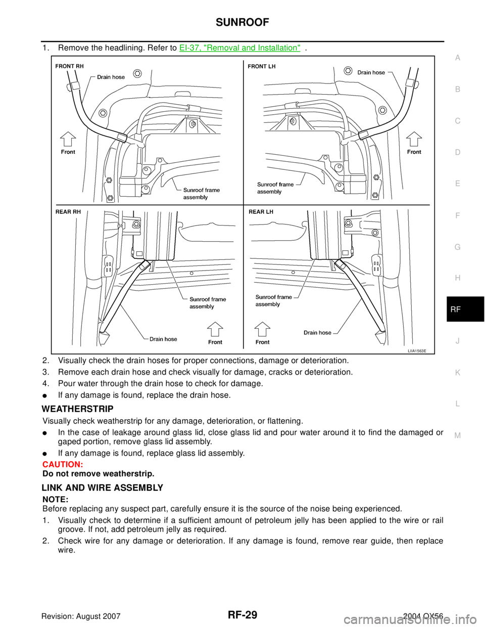
1. Remove the headlining. Refer to EI-37, "Removal and Installation" .
2. Visually check the drain hoses for proper connections, damage or deterioration.
3. Remove each drain hose and check visually for damage, cracks or deterioration.
4. Pour water through the drain hose to check for damage.
�If any damage is found, replace the drain hose.
WEATHERSTRIP
Visually check weatherstrip for any damage, deterioration, or flattening.
�In the case of leakage around glass lid, close glass lid and pour water around it to find the damaged or
gaped portion, remove glass lid assembly.
�If any damage is found, replace glass lid assembly.
CAUTION:
Do not remove weatherstrip.
LINK AND WIRE ASSEMBLY
NOTE:
Before replacing any suspect part, carefully ensure it is the source of the noise being experienced.
1. Visually check to determine if a sufficient amount of petroleum jelly has been applied to the wire or rail
groove. If not, add petroleum jelly as required.
2. Check wire for any damage or deterioration. If any damage is found, remove rear guide, then replace
wire.
LIIA1563E
Page 2832 of 3371
RFD-1
REAR FINAL DRIVE
D DRIVELINE/AXLE
CONTENTS
C
E
F
G
H
I
J
K
L
M
SECTION RFD
A
B
RFD
Revision: August 20072004 QX56 PREPARATION ........................................................... 2
Special Service Tools ............................................... 2
Commercial Service Tools ........................................ 4
NOISE, VIBRATION, AND HARSHNESS (NVH)
TROUBLESHOOTING ................................................ 5
NVH Troubleshooting Chart ..................................... 5
FRONT OIL SEAL ...................................................... 6
Removal and Installation .......................................... 6
REMOVAL ............................................................. 6
INSTALLATION ..................................................... 7
SIDE OIL SEAL .......................................................... 8
Removal and Installation .......................................... 8
REMOVAL ............................................................. 8
INSTALLATION ..................................................... 8
REAR FINAL DRIVE ASSEMBLY ............................ 10
Removal and Installation ........................................ 10
REMOVAL ........................................................... 10
INSTALLATION ....................................................11
Components ............................................................11
Pre-Inspection ........................................................ 12
TOTAL PRELOAD ............................................... 12
DRIVE GEAR TO DRIVE PINION BACKLASH ... 12
DRIVE GEAR RUNOUT ...................................... 12
COMPANION FLANGE RUNOUT ...................... 13
TOOTH CONTACT .............................................. 13
Disassembly and Assembly ................................... 13
REMOVAL OF DIFFERENTIAL CASE ASSEM-BLY ...................................................................... 13
REMOVAL OF DRIVE PINION ASSEMBLY ........ 14
DISASSEMBLY OF DIFFERENTIAL CASE
ASSEMBLY ......................................................... 16
INSPECTION ...................................................... 17
ADJUSTMENT OF DIFFERENTIAL CASE ......... 17
SIDE BEARING PRELOAD ................................. 18
TOOTH CONTACT .............................................. 19
ASSEMBLY OF DIFFERENTIAL CASE ASSEM-
BLY ...................................................................... 20
INSTALLATION OF DRIVE PINION ASSEMBLY ... 21
INSTALLATION OF DIFFERENTIAL CASE
ASSEMBLY ......................................................... 23
SERVICE DATA AND SPECIFICATIONS (SDS) ...... 26
General Specifications ............................................ 26
Drive Gear Runout .................................................. 26
Side Gear Adjustment ............................................ 26
AVAILABLE SIDE GEAR THRUST WASHERS ... 26
Drive Pinion Height Adjustment .............................. 26
AVAILABLE PINION HEIGHT ADJUSTING
WASHERS .......................................................... 26
Drive Pinion Preload Adjustment ............................ 26
Side Bearing Preload Adjustment ........................... 27
SIDE BEARING ADJUSTING WASHERS .......... 27
Total Preload Adjustment ........................................ 27
Page 2833 of 3371
RFD-2
PREPARATION
Revision: August 20072004 QX56
PREPARATIONPFP:00002
Special Service ToolsEDS0 02 JH
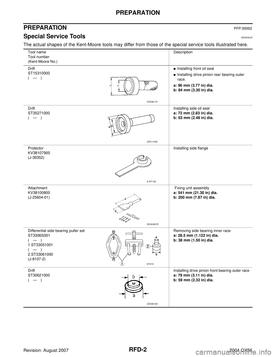
The actual shapes of the Kent-Moore tools may differ from those of the special service tools illustrated here.
Tool name
Tool number
(Kent-Moore No.)Description
Drift
ST15310000
(—)
�Installing front oil seal
�Installing drive pinion rear bearing outer
race.
a: 96 mm (3.77 in) dia.
b: 84 mm (3.30 in) dia.
Drift
ST35271000
(—)Installing side oil seal
a: 72 mm (2.83 in) dia.
b: 63 mm (2.48 in) dia.
Protector
KV38107900
(J-39352)Installing side flange
Attachment
KV38100800
(J-25604-01) Fixing unit assembly
a: 541 mm (21.30 in) dia.
b: 200 mm (7.87 in) dia.
Differential side bearing puller set
ST3306S001
(—)
1.ST33051001
(—)
2.ST33061000
(J-8107-2)Removing side bearing inner race
a: 28.5 mm (1.122 in) dia.
b: 38 mm (1.50 in) dia.
Drift
ST30621000
(—)Installing drive pinion front bearing outer race
a: 79 mm (3.11 in) dia.
b: 59 mm (2.32 in) dia.
ZZA0811D
ZZA1143D
S-NT129
SDIA0267E
NT072
ZZA0810D
Page 2834 of 3371
PREPARATION
RFD-3
C
E
F
G
H
I
J
K
L
MA
B
RFD
Revision: August 20072004 QX56
Drift
KV38100200
(J-26233)Installing side bearing inner race
a: 65 mm (2.55 in) dia.
b: 49 mm (1.92 in) dia.
Drive pinion flange wrench
KV40104000
(—)Removing and installing drive pinion nut
a: 85 mm (3.35 in) dia.
b: 65 mm (2.56 in) dia.
Slide hammer
ST36230000
(J-25840-A)Removing side flange
Axle stand
KV40104100
(—)Removing side flange
Slide hammer
HT72400000
(—)Removing differential case assembly
Drift
ST35325000
(—)Installing drive pinion rear bearing outer race
(use with ST30621000)
Preload gauge
ST3127S000
(J-25765-A)
1. Torque wrench
GG91030000
(J-25765)
2. Socket adapter (1/2 in)
HT62940000
(—)
3. Socket adapter (3/8 in)
HT62900000
(—)Measuring pinion bearing preload and total
preload Tool name
Tool number
(Kent-Moore No.)Description
ZZA1143D
NT659
ZZA0803D
ZZA0804D
S-NT125
S-NT090
NT124
Page 2835 of 3371
RFD-4
PREPARATION
Revision: August 20072004 QX56
Commercial Service ToolsEDS002JI
Side bearing outer race puller
ST33290001
(J-34286)Removing front oil seal
Drift
ST33081000
(—)Installing side bearing
a: 43 mm (1.69 in) dia.
b: 33.5 mm (1.31 in) dia.
Bearing puller
ST30021000
(—)Removing drive pinion rear bearing inner
race
Drift
ST30022000
(—)Installing drive pinion rear bearing inner race
a: 110 mm (4.33 in) dia.
b: 46 mm (1.81 in) dia. Tool name
Tool number
(Kent-Moore No.)Description
ZZA0601D
ZZA0810D
ZZA0700D
ZZA0920D
Tool nameDescription
Power toolRemoving bolts and nuts
PBIC0190E
Page 2837 of 3371
RFD-6
FRONT OIL SEAL
Revision: August 20072004 QX56
FRONT OIL SEALPFP:38189
Removal and InstallationEDS002JK
REMOVAL
1. Remove the drive shaft inside flange bolts to disconnect the rear drive shafts from the rear final drive.
Support the rear drive shafts using suitable wire.
NOTE:
Disconnecting the rear drive shafts is necessary to measure the total preload accurately.
2. Remove the rear propeller shaft. Refer to PR-8, "
Removal and Installation" .
CAUTION:
Do not damage the propeller shaft tube.
3. Check the total preload. Refer to RFD-12, "
TOTAL PRELOAD" .
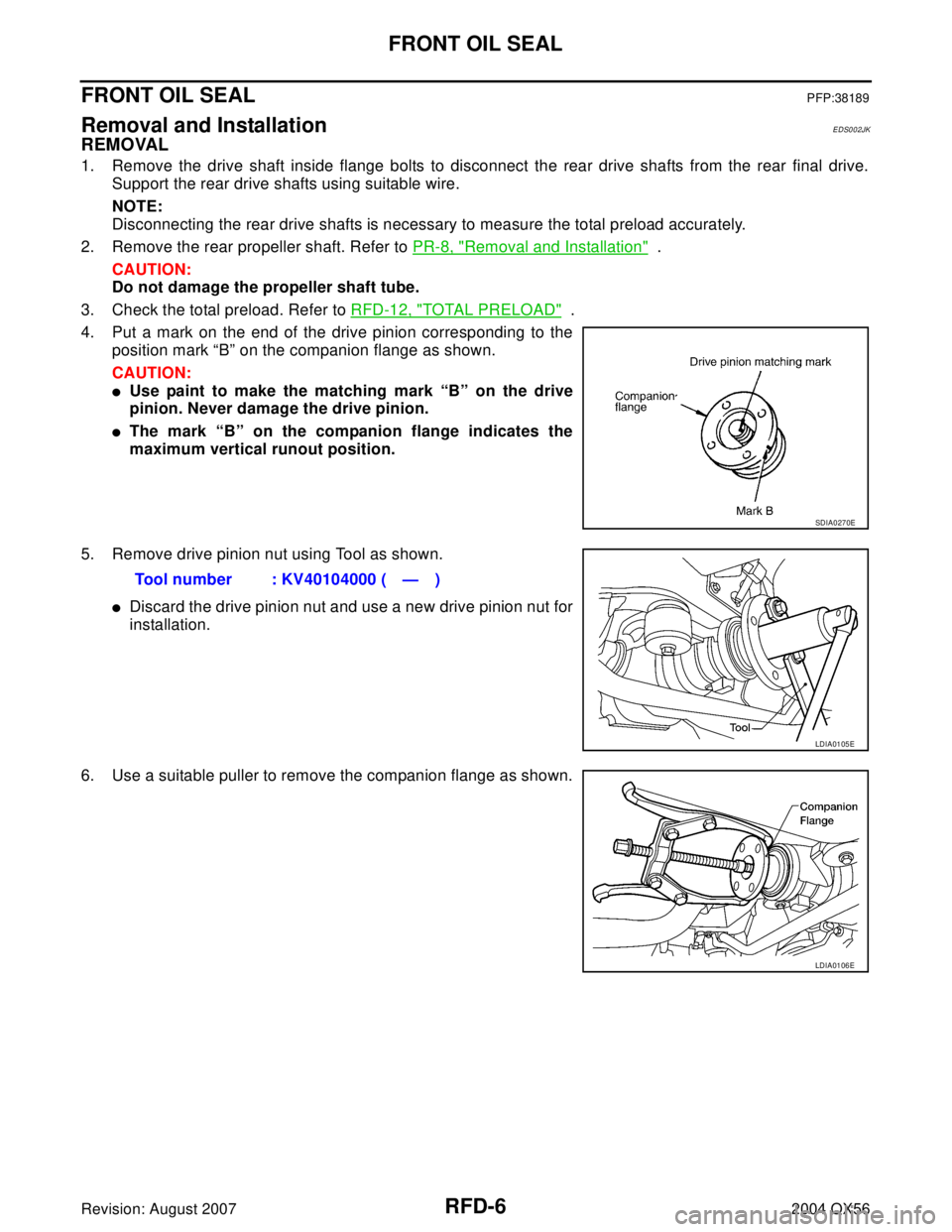
4. Put a mark on the end of the drive pinion corresponding to the
position mark “B” on the companion flange as shown.
CAUTION:
�Use paint to make the matching mark “B” on the drive
pinion. Never damage the drive pinion.
�The mark “B” on the companion flange indicates the
maximum vertical runout position.
5. Remove drive pinion nut using Tool as shown.
�Discard the drive pinion nut and use a new drive pinion nut for
installation.
6. Use a suitable puller to remove the companion flange as shown.
SDIA0270E
Tool number : KV40104000 ( — )
LDIA0105E
LDIA0106E
Page 2838 of 3371
FRONT OIL SEAL
RFD-7
C
E
F
G
H
I
J
K
L
MA
B
RFD
Revision: August 20072004 QX56
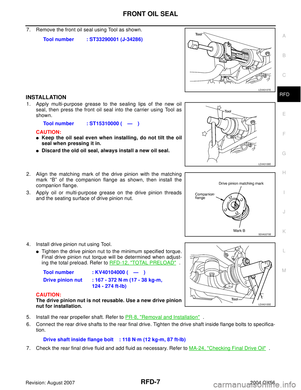
7. Remove the front oil seal using Tool as shown.
INSTALLATION
1. Apply multi-purpose grease to the sealing lips of the new oil
seal, then press the front oil seal into the carrier using Tool as
shown.
CAUTION:
�Keep the oil seal even when installing, do not tilt the oil
seal when pressing it in.
�Discard the old oil seal, always install a new oil seal.
2. Align the matching mark of the drive pinion with the matching
mark “B” of the companion flange as shown, then install the
companion flange.
3. Apply oil or multi-purpose grease on the drive pinion threads
and the seating surface of drive pinion nut.
4. Install drive pinion nut using Tool.
�Tighten the drive pinion nut to the minimum specified torque.
Final drive pinion nut torque will be determined when adjust-
ing the total preload. Refer to RFD-12, "
TOTAL PRELOAD" .
CAUTION:
The drive pinion nut is not reusable. Use a new drive pinion
nut for installation.
5. Install the rear propeller shaft. Refer to PR-8, "
Removal and Installation" .
6. Connect the rear drive shafts to the rear final drive. Tighten the drive shaft inside flange bolts to specifica-
tion.
7. Check the rear final drive fluid and add fluid as necessary. Refer to MA-24, "
Checking Final Drive Oil" . Tool number : ST33290001 (J-34286)
LDIA0107E
Tool number : ST15310000 ( — )
LDIA0108E
SDIA0270E
Tool number : KV40104000 ( — )
Drive pinion nut : 167 - 372 N·m (17 - 38 kg-m,
124 - 274 ft-lb)
LDIA0105E
Drive shaft inside flange bolt : 118 N·m (12 kg-m, 87 ft-lb)