Page 2817 of 3371
EIS002WQ
CONSULT-II can display each diagnostic item using the diagnostic test modes shown following.
CONSULT-II OPERATION
CAUTION")
RF-16
SUNROOF
Revision: August 20072004 QX56
CONSULT-II Function (BCM)EIS002WQ
CONSULT-II can display each diagnostic item using the diagnostic test modes shown following.
CONSULT-II OPERATION
CAUTION:
If CONSULT-II is used with no connection of CONSULT-II CONVERTER, malfunctions might be
detected in self-diagnosis depending on control unit which carries out CAN communication.
1. With the ignition switch OFF, connect CONSULT-II and CON-
SULT-II CONVERTER to the data link connector, then turn igni-
tion switch ON.
2. Touch "START (NISSAN BASED VHCL)".
3. Touch "BCM".
If "BCM" is not indicated, go to GI-39, "
CONSULT-II Data Link
Connector (DLC) Circuit" .
BCM diagnostic
test itemDiagnostic mode Description
Inspection by partWORK SUPPORTSupports inspections and adjustments. Commands are transmitted to the BCM
for setting the status suitable for required operation, input/output signals are
received from the BCM and received data is displayed.
DATA MONITOR Displays BCM input/output data in real time.
ACTIVE TEST Operation of electrical loads can be checked by sending drive signal to them.
SELF-DIAG RESULTS Displays BCM self-diagnosis results.
CAN DIAG SUPPORT MNTR The result of transmit/receive diagnosis of CAN communication can be read.
ECU PART NUMBER BCM part number can be read.
CONFIGURATION Performs BCM configuration read/write functions.
BBIA0369E
BCIA0029E
BCIA0030E
Page 2819 of 3371

RF-18
SUNROOF
Revision: August 20072004 QX56
BCM Power Supply and Ground Circuit CheckEIS002WV
1. CHECK FUSE
Check the following BCM fuse and fusible link.
NOTE:
Refer to RF-10, "
Component Parts and Harness Connector Location" .
OK or NG
OK >> GO TO 2.
NG >> If fuse is blown, be sure to eliminate cause of problem before installing new fuse. Refer to PG-4,
"POWER SUPPLY ROUTING CIRCUIT" .
2. CHECK POWER SUPPLY CIRCUIT
1. Turn ignition switch OFF.
2. Disconnect BCM connectors.
3. Check voltage between BCM connectors M18 and M20 termi-
nals 38, 70 and ground.
OK or NG
OK >> GO TO 3.
NG >> Repair or replace harness.
3. CHECK GROUND CIRCUIT
Check continuity between BCM connector M20 terminals 67 and
ground.
OK or NG
OK >> Power supply and ground circuits are OK.
NG >> Repair or replace harness.
Retained power operation does not operate properly.1. Check the retained power operation mode settingRF-112. BCM power supply and ground circuit checkRF-18
3. Door switch checkRF-22
4. Replace sunroof motor assemblyRF-27
Motor does not stop at the sunroof fully-open or fully-closed
position.1. Initialization procedure checkRF-11
2. Replace sunroof motor assemblyRF-27
Sunroof does not do the interruption detection. 1. Replace sunroof motor assemblyRF-27
Symptom Diagnostic procedure and repair order Refer to page
Component Parts Terminal No. (SIGNAL) Ampere No. Location
BCM38 (IGN power supply) 10A 59 Fuse and relay box
70 (BAT power supply) 50A f Fuse and fusible link box
ConnectorTerminals
(Wire color)
ConditionVoltage (V)
(Approx.)
(+) (–)
M18 38 (W/L)
GroundIgnition switch ON
Battery voltage
M20 70 (W/B) Ignition switch OFF
WIIA0229E
Connector Terminals (Wire color) Continuity
M20 67 (B) Ground Yes
WIIA0230E
Page 2822 of 3371

SUNROOF
RF-21
C
D
E
F
G
H
J
K
L
MA
B
RF
Revision: August 20072004 QX56
2. CHECK SUNROOF MOTOR CIRCUIT HARNESS
1. Turn ignition switch OFF.
2. Disconnect BCM connector.
3. Check continuity between BCM connector M20 terminals 68 and
69 and sunroof motor assembly connector R4 terminals 1 and 5.
4. Check continuity between BCM connector M20 terminal 68, 69
and ground.
OK or NG
OK >> Replace BCM. Refer to BCS-19, "Removal and Installation of BCM" .
NG >> Repair or replace harness between BCM and sunroof motor assembly.
3. CHECK GROUND CIRCUIT
Check continuity between sunroof motor assembly connector R4 terminal 7 and ground.
OK or NG
OK >> Sunroof motor assembly power supply and ground cir-
cuits are OK.
NG >> Repair or replace harness.68 (W/L) - 1 (W/L) : Continuity should exist.
69 (W/R) - 5 (W/R) : Continuity should exist.
68 (W/L) - Ground : Continuity should not exist.
69 (W/R) - Ground : Continuity should not exist.
LIIA2251E
7 (B) - Ground : Continuity should exist.
WIIA0251E
Page 2824 of 3371
SUNROOF
RF-23
C
D
E
F
G
H
J
K
L
MA
B
RF
Revision: August 20072004 QX56
3. CHECK DOOR SWITCH
Check continuity between each door switch terminal 2 and body ground part of door switch.
OK or NG
OK >> GO TO 4.
NG >> Replace malfunctioning door switch.
4. CHECK BCM OUTPUT SIGNAL
1. Connect BCM connector.
2. Check voltage between BCM connector M18 terminal 12, M19 terminal 47 and ground.
OK or NG
OK >> Check the condition of the harness and the connector.
NG >> Replace BCM. Refer to BCS-19, "
Removal and Installa-
tion of BCM" .
Terminal Condition Continuity
2Body ground part
of door switchDoor switch pushed No
Door switch released Yes
WIIA0289E
12 (R/L) - Ground : Battery voltage
47 (SB) - Ground : Battery voltage
WIIA0234E
Page 2825 of 3371

RF-24
SUNROOF
Revision: August 20072004 QX56
Fitting AdjustmentEIS002WZ
GAP ADJUSTMENT
NOTE:
If any gap or height difference between glass lid and roof panel is found, check glass lid fit and adjust as fol-
lows:
1. Open sunshade assembly.
2. Loosen glass lid securing screws (2 each on left and right sides), then tilt glass lid down.
3. Manually adjust glass lid from outside of vehicle so it resembles "A-A" as shown in the figure.
4. After adjusting glass lid tilt glass lid up and tighten screws.
5. Tilt glass lid up and down several times to check that it moves smoothly.
HEIGHT DIFFERENCE ADJUSTMENT
1. Tilt glass lid up and down.
2. Check height difference between roof panel and glass lid, and compare to “A-A”.
Removal and InstallationEIS002X0
�After any adjustment, check sunroof operation and glass lid alignment.
�Handle glass lid with care so not to cause damage.
�For easier installation, mark each point before removal.
CAUTION:
�Always work with a helper.
�Before removal, fully close the glass lid assembly. Then, after removal, do not move the motor
assembly.
WIIA0760E
Page 2826 of 3371
SUNROOF
RF-25
C
D
E
F
G
H
J
K
L
MA
B
RF
Revision: August 20072004 QX56
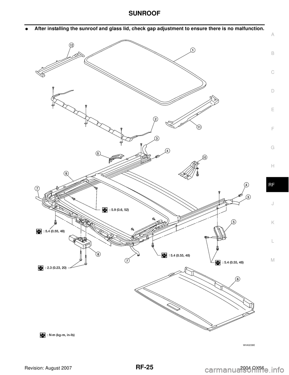
�After installing the sunroof and glass lid, check gap adjustment to ensure there is no malfunction.
WIIA0238E
Page 2827 of 3371

RF-26
SUNROOF
Revision: August 20072004 QX56
SUNROOF UNIT
Removal
CAUTION:
�Always work with a helper.
�When taking sunroof unit out, use shop cloths to protect the seats and trim from damage.
�After installing the sunroof unit and glass lid, be sure to check gap adjustment to ensure there is
no malfunction.
1. Remove headlining. Refer to EI-37, "
HEADLINING" .
2. Remove the sunroof glass lid. Refer to RF-26, "
GLASS LID" .
3. Remove overhead console bracket.
4. Disconnect the drain hoses.
5. Remove front sunroof bolts.
6. Remove rear sunroof bracket bolts.
7. Remove the side bolts and the sunroof unit.
Installation
1. Position the sunroof frame assembly and install the side bolts.
2. Install the rear brackets.
3. Install the front mounting bolts.
4. Connect drain hoses.
5. Install the overhead console bracket.
6. Install the sunroof glass lid. Refer to RF-26, "
GLASS LID" .
7. Install headlining. Refer to EI-37, "
HEADLINING" .
GLASS LID
Removal
1. Open sunshade.
2. Ensure glass lid is closed.
3. Remove side cover LH and RH.
4. Remove the screws securing glass lid to the sunroof frame
assembly.
5. Remove the glass lid assembly.
Installation
1. Position glass lid to sunroof assembly.
2. Install the glass lid assembly screws. (First tighten left front bolt, then tighten right rear bolt on glass lid to
prevent lid from moving while tightening other bolts.)
3. Adjust the sunroof glass. Refer to RF-24, "
Fitting Adjustment" .
4. Install side cover LH and RH.
1. Glass lid assembly 2. Wind deflector 3. Rear drain hoses
4. Shade stoppers 5. Sunroof bracket 6. Sunshade assembly
7. Front drain hoses 8. Sunroof motor assembly 9. Sunroof frame assembly
10. Overhead console bracket 11. Side cover LH 12. Side cover RH
WIIA0252E
Page 2828 of 3371

SUNROOF
RF-27
C
D
E
F
G
H
J
K
L
MA
B
RF
Revision: August 20072004 QX56
WIND DEFLECTOR
Removal and Installation
1. Open the sunroof.
2. Remove screws from the left, center, and right side wind deflec-
tor holders.
3. Remove the wind deflector from the sunroof frame assembly.
Installation is in the reverse order of removal.
SUNSHADE
Removal and Installation
1. Remove the sunroof frame assembly. Refer to RF-26, "SUNROOF UNIT" .
2. Remove the sunshade stoppers (2 points) from the rear end of
the sunroof frame assembly.
3. Remove the sunshade assembly from the rear end of the sun-
roof frame assembly.
Installation is in the reverse order of removal.
SUNROOF MOTOR
Removal
CAUTION:
�When removing the sunroof motor, be sure that the sunroof is in the fully closed position.
�Never run the removed motor as a single unit.
1. Position the sunroof assembly in the fully closed position.
2. Remove the front roof console assembly. Refer to EI-37, "
HEADLINING" .
3. Disconnect the harness connector from the sunroof motor
assembly.
4. Remove the mounting screws and the sunroof motor assembly.
Installation
CAUTION:
Before installing the sunroof motor assembly, be sure to place the link and wire assembly in the sym-
metrical and fully closed position.
LIIA1099E
SBT 2 51 A
LIIA0270E